1. Inleiding
This manual provides essential information for the proper installation, operation, and maintenance of the Generic W19-94 01E Refrigerator Main PCB Power Control Board. This board is designed for compatibility with Haitech HRF-AM32 refrigerator models. Please read this manual thoroughly before proceeding with any procedures to ensure safe and correct handling of the product.
2. Veiligheidsinligting
Waarskuwing: Electrical components can cause serious injury or death. Installation and replacement of this part should only be performed by a qualified technician. Always disconnect power to the appliance before attempting any repair or installation.
- Ensure the refrigerator is completely unplugged from the power source before beginning work.
- Wear appropriate personal protective equipment, including insulated gloves.
- Handle the PCB by its edges to avoid damaging components or introducing static electricity.
- Do not attempt to repair a damaged board; replace it with a new, compatible unit.
3. Produk verbyview
The W19-94 01E Main PCB Power Control Board is a critical component responsible for managing the electrical operations and power distribution within compatible refrigerators. It ensures the proper functioning of various refrigerator systems, including temperature control, compressor operation, and defrost cycles.
Sleutel kenmerke:
- Verenigbaarheid: Specifically designed for HRF-AM32 models, matching W19-94 01E specifications.
- Funksie: Manages the appliance's power control system and electrical operations.
- Ontwerp: Crafted to align with the structural and operational specifications of the HRF-AM32 refrigerator setup.
- Aansoek: Suitable for integration in the HRF-AM32 refrigerator to maintain proper power control functionality.
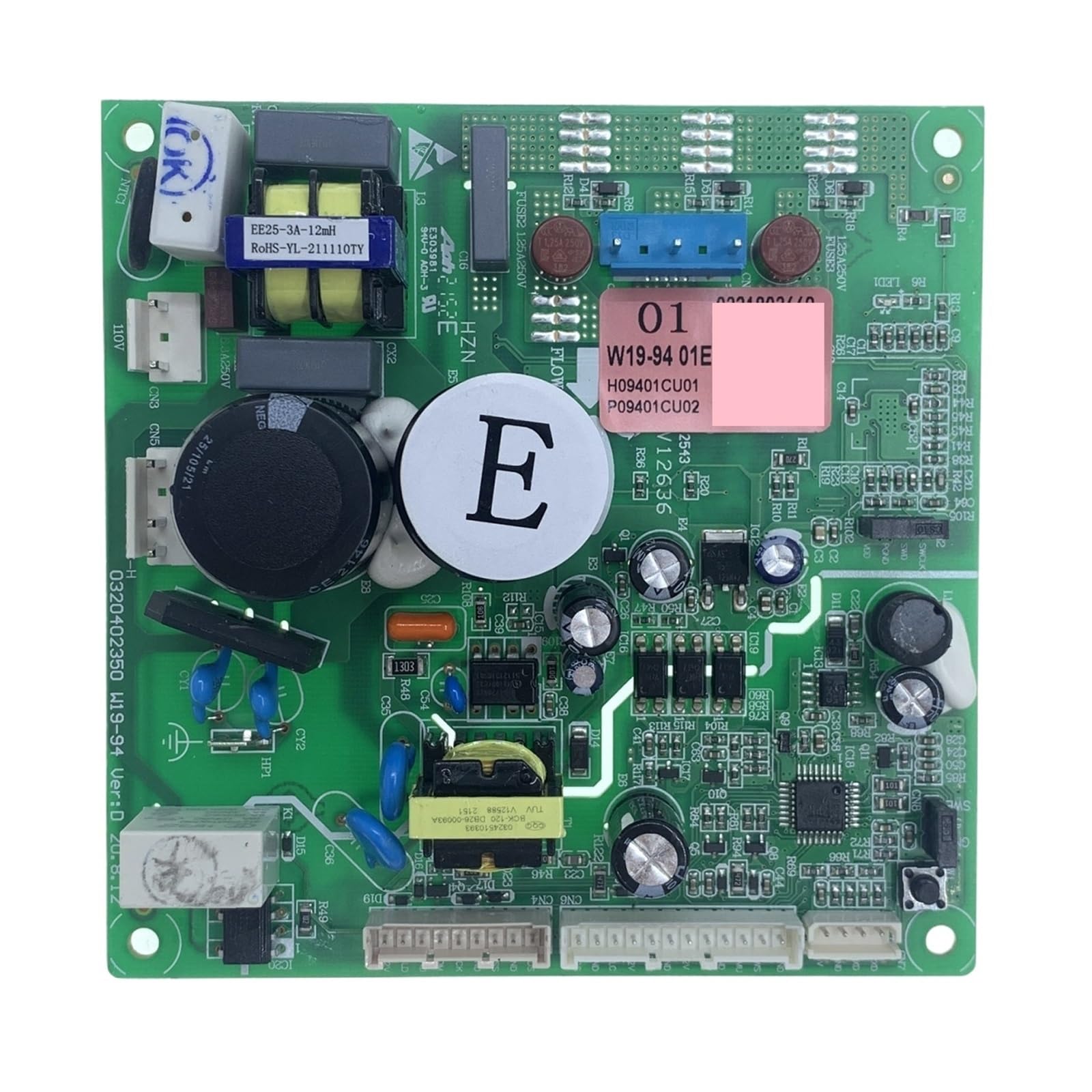
Figuur 1: W19-94 01E Refrigerator Main PCB Power Control Board. This image displays the green circuit board of the W19-94 01E Refrigerator Main PCB Power Control Board. Various electronic components such as integrated circuits (ICs), resistors, capacitors, and diodes are visible across its surface. The board features multiple solder points and traces, indicating complex circuitry for managing refrigerator functions. Connectors for power input and output, as well as communication lines, are also present.
4. Opstelling en installering
Installation of the W19-94 01E Main PCB Power Control Board requires careful attention to electrical connections and component placement. It is strongly recommended that this procedure be performed by a certified appliance technician.
Installasie stappe:
- Ontkoppel krag: Unplug the refrigerator from the wall outlet to ensure no electrical current is flowing.
- Toegangsbeheerbord: Locate and remove the access panel that covers the existing control board. This location varies by refrigerator model (refer to your refrigerator's service manual).
- Dokumentverbindings: Before disconnecting any wires, take clear photographs or make a detailed diagram of all wire connections to the old control board. This is crucial for correct reassembly.
- Ontkoppel Drade: Carefully disconnect all wire harnesses and connectors from the old control board. Note any specific locking mechanisms.
- Verwyder ou bord: Skroef of knip die ou beheerbord van sy monteerhakies los.
- Installeer nuwe bord: Position the new W19-94 01E control board in the same location and secure it using the original screws or clips.
- Herkoppel Drade: Using your photographs or diagrams, carefully reconnect all wire harnesses and connectors to the new board. Ensure each connection is secure and correctly seated.
- Veilige Toegangspaneel: Vervang die toegangspaneel en maak seker dat alle skroewe vasgedraai is.
- Herstel krag: Steek die yskas terug in die muuraansluiting.
- Toetsfunksionaliteit: Verify that the refrigerator powers on and operates correctly. Check for proper cooling, light operation, and any error codes.
5. Bedryfsinstruksies
The W19-94 01E Main PCB Power Control Board operates automatically once installed and power is supplied to the refrigerator. It continuously monitors and controls the various electrical systems to maintain optimal performance of the appliance. There are no direct user-operable controls on the board itself.
Ensure the refrigerator's external controls (e.g., temperature settings, ice maker functions) are set according to your desired operational parameters. The control board will execute these commands by managing the power to the relevant components.
6. Onderhoud
The W19-94 01E Main PCB Power Control Board is designed for long-term reliability and typically requires minimal maintenance. However, periodic inspection can help ensure its longevity and proper function.
Onderhoudsriglyne:
- Kragontkoppeling: Always disconnect power to the refrigerator before performing any inspection or cleaning.
- Visuele inspeksie: Periodically (e.g., annually, during other appliance maintenance) inspect the board for any signs of physical damage, such as burn marks, swollen components, or loose connections.
- Skoonmaak: If dust or debris accumulates on the board, gently clean it using a soft, dry brush or compressed air. Do not use liquids or abrasive cleaners.
- Omgewingstoestande: Ensure the area around the control board remains dry and free from excessive humidity or temperature fluctuations, which can degrade electronic components.
7. Probleemoplossing
If your refrigerator experiences issues after the installation of the W19-94 01E Main PCB Power Control Board, or if you suspect the board is malfunctioning, consider the following troubleshooting steps. Due to the complexity of refrigerator electronics, professional diagnosis is often required.
Algemene kwessies en oplossings:
- Yskas skakel nie aan nie:
- Kontroleer of die yskas behoorlik in 'n werkende stopcontact ingeprop is.
- Verify the circuit breaker for the refrigerator has not tripped.
- Maak seker dat alle draadverbindings na die beheerbord stewig en korrek geplaas is.
- Inconsistent Cooling or Functionality:
- Bevestig dat die yskas se temperatuurinstellings korrek is.
- Inspect for any visible damage or loose components on the control board (after disconnecting power).
- Consult a qualified technician for diagnostic testing of the control board and other refrigerator components.
- Foutkodes wat vertoon word:
- Refer to your specific refrigerator model's user manual for the meaning of any displayed error codes.
- Some error codes may indicate a fault with the control board or a component it manages.
If troubleshooting steps do not resolve the issue, contact a professional appliance repair service.
8. Spesifikasies
| Spesifikasie | Detail |
|---|---|
| Modelnommer | W19-94 01E |
| Tik | Yskasonderdele |
| Verenigbaarheid | Haitech HRF-AM32 |
| Item gewig | 1.76 onse |
| Produk afmetings | 3.94 x 3.94 x 3.94 duim |
| Voltage | 1 Kilovolts (Note: This may refer to a maximum rating or a general category value, not typical operating voltage.) |
| Sertifisering | UL |
| ASIN | B0GD1GV5R5 |
9. Waarborg en Ondersteuning
Specific warranty terms for the W19-94 01E Refrigerator Main PCB Power Control Board are provided by the seller or manufacturer at the time of purchase. Please retain your proof of purchase for any warranty claims.
For technical support or inquiries regarding this product, please contact the retailer or the manufacturer directly. Contact information is typically available on your purchase receipt or the product packaging.


