eletechsup KC23C01
eletechsup KC23C01 Multifunction Pulse Counter Switch Adjustable Timer Delay Relay Module User Manual
Model: KC23C01 | Brand: eletechsup
Produk verbyview
The eletechsup KC23C01 is a versatile multifunction pulse counter switch and adjustable timer delay relay module. It supports DC 5V, 12V, or 24V operation and offers various working modes for pulse counting and general delay relay functions. This module is designed for industrial control applications requiring precise timing and counting capabilities.
Spesifikasies
| Parameter | Waarde |
|---|---|
| Werk Voltage | DC 12V (DC 5V/ DC24V optional) |
| Working Current (Digital tube OFF) | Relay OFF: 6mA, Relay ON: 35mA |
| Working Current (Digital tube ON) | Relay OFF: 29mA, Relay ON: 56mA |
| Invoerpoort | Optocoupler isolation input, compatible with NPN/PNP switch signal (5-24V) |
| Uitvoerpoort | 10A relay (NO, COM, NC terminals) |
| Relay Load Capacity | 10A/250VAC; 10A/30VDC |
| Vertragingstydreeks | 0.1s - 9999999.9s (approx. 115.7 days), Step 0.1s, Accuracy 0.01s |
| Pulse Count Value Range | 0 - 9999 |
| Afmetings | 74.4 mm x 40.5 mm x 19.6 mm |
| Gewig | 29.2g |
Produk Kenmerke
- Wide delay time range from 0.1 seconds to 9,999,999.9 seconds.
- Adjustable pulse count value from 0 to 9999.
- Twelve distinct working modes (F00-F05 for delay, F10-F15 for pulse counting), including 8 modes with cycle settings.
- Three trigger signal input methods: no external source, NPN source, and PNP source.
- Three operational states: Working State, Power-Saving Status, and Setting State.
Komponent Identifikasie
Familiarize yourself with the main components of the KC23C01 module:
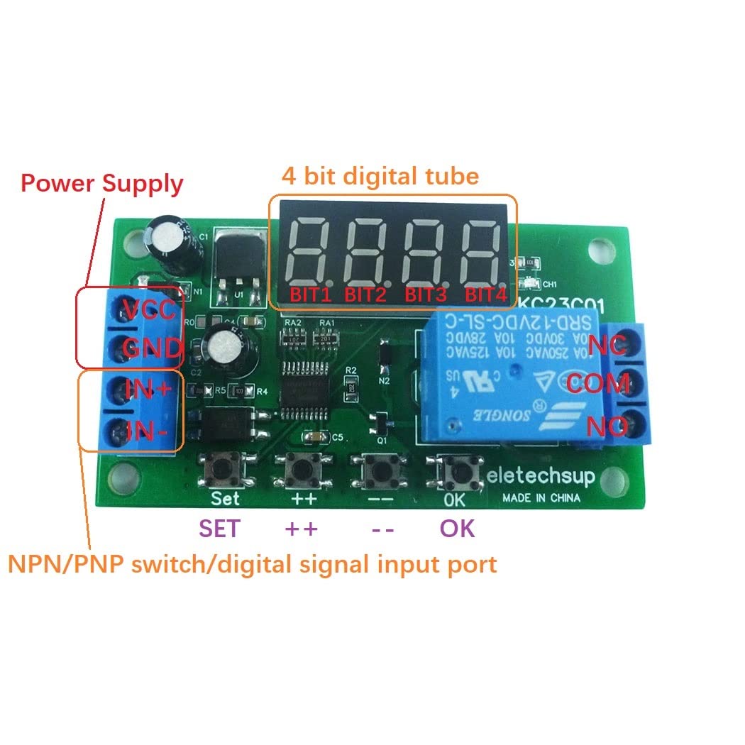
This image illustrates the key components of the KC23C01 module, including the power supply terminals (VCC, GND), the 4-digit digital display, the NPN/PNP switch/digital signal input terminals (IN+, IN-), and the control buttons: SET, ++ (increment), -- (decrement), and OK.
- Kragtoevoer: VCC and GND terminals for connecting DC 5V/12V/24V power.
- Digital Tube: A 4-digit display showing time, count, or mode information.
- Invoerpoort: IN+ and IN- terminals for NPN/PNP switch or digital signal input.
- Uitsetpoort: NO, COM, NC terminals for relay output.
- Knoppies: SET, ++, --, OK for navigation and parameter adjustment.
Bedradingmetodes
The module supports three primary methods for trigger signal input. Ensure correct wiring for your application.

This image displays three different wiring configurations for the trigger signal input. The first diagram illustrates a setup without an external signal source, typically using a push-button. The second diagram shows how to connect an NPN type signal source, and the third diagram details the connection for a PNP type signal source. All diagrams also show the power input and how to connect a load to the relay output.
- No External Signal Source Required: Connect a switch or button between the IN+ terminal and GND. When the button is pressed, it provides a low-level trigger.
- Trigger with NPN Source: Connect the NPN signal output to the IN+ terminal. The NPN sensor provides a low-level signal (connects IN+ to GND) when triggered.
- Trigger with PNP Signal Source: Connect the PNP signal output to the IN- terminal. The PNP sensor provides a high-level signal (connects IN- to VCC) when triggered.
Laai verbinding: The relay output (NO, COM, NC) can control loads operating on DC 1-110V or AC 85-265V, up to 10A.
Opstelling en werking
Knoppie funksies:
- Kort druk: Press and release the key within 2 seconds.
- Lang druk: Press and hold the key for more than 2 seconds.
Operasionele state:
- Werkende staat: The default state after power-on.
- F00-F05 modes display remaining time.
- F10-F15 modes display remaining time and pulse count value.
- If remaining time exceeds four digits, short press the 'OK' button to scroll and display the full time.
- Instellingstoestand: Used to modify parameters.
- Short press 'SET' to enter.
- Short press 'SET' again to cycle through parameters.
- Short press '++' or '--' to modify the current parameter value.
- Short press 'OK' to save parameters and exit the Setting State.
- Belangrik: After setting parameters, the module must be powered off and on again for changes to take effect.
- Query Status: Gewoond aan view parameters without modifying them.
- Short press 'SET' to enter (if not already in Setting State).
- Short press 'SET' again to cycle through parameters.
- Short press 'OK' to exit the Query Status.
- Power-Saving Status: Turns off the digital display to conserve power while other functions operate normally.
- To enter: Long press the 'OK' button for 5 seconds.
- To exit: Long press the 'OK' button for 5 seconds again.
- In Power-Saving Status, you can still enter Setting or Query states. The module will automatically return to Power-Saving Status after 20 seconds of no key operation.
- After power-on, the digital tube displays for 20 seconds before potentially entering Power-Saving Status if previously enabled.
Working Modes (F00-F05, F10-F15)
The module offers 12 distinct working modes, categorized into general delay and pulse counting functions.
- F00-F05: Single-shot pulse control modes, functioning as general delay relays. These modes primarily focus on timing operations.
- F10-F15: Pulse counting control modes. These modes use the input port to count pulses and control the relay based on the set count value.
- Eight of these modes include options for setting the number of cycles for repetitive operations.
Refer to the detailed mode descriptions within the module's interface for specific parameter settings for each mode.
Probleemoplossing
- Inexplicable Problems: If the module behaves unexpectedly, first try cycling the power (power off, then power on again). This ensures that any recently changed parameters are properly loaded.
- Aanhoudende kwessies: If power cycling does not resolve the problem, perform a factory reset.
- Fabrieksinstelling: Press and hold the '++' and '--' buttons simultaneously for 3 seconds. This will restore all settings to their default values and turn off the digital tube display.
- After a factory reset, power cycle the module again for the default parameters to take effect.
- Digital Tube Display Issue: If the digital tube does not display after power-on, it might be in Power-Saving Status or the display was turned off during a factory reset. Long press 'OK' for 5 seconds to toggle Power-Saving Status, or perform a factory reset and then power cycle.
Onderhoud
The eletechsup KC23C01 module is designed for reliable operation with minimal maintenance. Keep the module clean and free from dust and moisture. Ensure proper ventilation if installed in an enclosure. Avoid exposing the module to extreme temperatures or corrosive environments.
Waarborg en Ondersteuning
For warranty information, technical support, or further assistance, please contact eletechsup customer service through the retailer where the product was purchased or refer to the official eletechsup webwebwerf vir kontakbesonderhede.
Ask a question about this manual
Ask about setup, troubleshooting, compatibility, parts, safety, or missing instructions. Manuals+ will review the question and use this page’s manual context to help answer it.