1. Inleiding
Thank you for choosing the MokerLink 8-Port Gigabit PoE Managed Switch. This device is designed to provide reliable and high-performance network connectivity with Power over Ethernet (PoE) capabilities. This manual will guide you through the installation, configuration, and operation of your new switch, ensuring optimal performance and longevity.
2. Pakketinhoud
Verify that all items are present and in good condition. If any items are missing or damaged, please contact your vendor.
- MokerLink 8-Port Gigabit PoE Managed Switch
- Kragadapter
- Vinnige Begingids

Image: The MokerLink 8-Port Gigabit PoE Managed Switch, its power adapter, and a quick start guide are shown packaged in a brown cardboard box.
3. Produk verbyview
3.1 Sleutelkenmerke
- 8 Gigabit Ports: Includes 7 Gigabit PoE Ethernet ports and 1 Gigabit Ethernet Uplink port.
- High PoE Power: Ports 1-7 support IEEE 802.3af/at, with each port providing up to 30W, and a total power supply of 96W.
- L2 Smart Managed: Supports Layer 2 Ethernet configurations such as VLAN, QoS, IGMP, link aggregation, loop protection, port mirroring, port isolation, and bandwidth control.
- Web GUI: Kragtig web-based graphical user interface for managing PoE ports, displaying PSE power supply status, and configuring PoE functions.
- Fanlose ontwerp: Ensures silent operation, suitable for various environments.
- Duursame metaalbehuising: Provides robust protection and multiple cooling holes for heat dissipation.
- 4KV Lightning Protection: Integrated protection against power surges.
- Muur monteerbaar: Flexible installation options.

Beeld: 'n Oorview of the MokerLink 8-Port Gigabit PoE Managed Switch, illustrating its features including IEEE 802.3af/at support, full Gigabit ports, web interface, wall mountable design, 4KV lightning protection, and L2 management capabilities.
3.2 Voor- en agterpaneel
The front panel features 7 PoE Gigabit ports, 1 Gigabit Uplink port, and LED indicators. The rear panel includes the DC power input and a grounding hole.

Beeld: Gedetailleerd view of the switch's front and rear panels. The front panel shows 7 Gigabit PoE ports (1-7) and 1 Gigabit Uplink port (8), along with PWR and Port indicators. The rear panel displays the DC input port (48-52V) and a grounding hole. A reset button is also visible on the front.
3.3 LED-aanwysers
- PWR (Power Indicator): Green light on indicates power is supplied; light off indicates no power.
- Port Indicator: Green light on indicates link is connected; light off indicates link is off; flashing indicates data transmitting.
4. Opstelling
4.1 Fisiese installasie
- Plasing: Place the switch on a stable, flat surface or mount it to a wall using appropriate hardware. Ensure adequate ventilation around the device.
- Aarding: Connect a grounding wire to the grounding hole on the rear panel of the switch for electrical safety.
- Kragverbinding: Connect the provided power adapter to the DC input port on the rear panel and then plug it into a power outlet. The PWR LED should illuminate.
4.2 Netwerkverbinding
- Opwaartse verbinding: Connect your router or main network device to the Gigabit Uplink port (Port 8) using a standard Ethernet cable.
- PoE-toestelverbinding: Connect your PoE-powered devices (e.g., IP cameras, wireless access points, VoIP phones) to any of the Gigabit PoE ports (Ports 1-7) using Ethernet cables. The switch will automatically detect and provide power to compliant devices.
- Non-PoE Device Connection: Non-PoE devices can also be connected to Ports 1-7, but they will not receive power.
5. Bedryfsinstruksies
5.1 Basiese werking
Once powered on and connected, the switch operates automatically. Data transmission will occur between connected devices. The port LEDs will indicate link status and activity.
5.2 Remote PoE Device Reboot
The managed features allow you to remotely power cycle PoE devices connected to the switch. This can be useful for troubleshooting or resetting devices without physical access.

Image: A diagram illustrating how to remotely reboot PoE devices. A laptop screen shows a 'PoE Port ON/OFF' interface, connected to the switch. The switch then controls the power to a connected camera, effectively turning it on or off.
6. Konfigurasie (Web GUI)
The MokerLink switch features a powerful web-based management interface for advanced configuration and monitoring.
6.1 Toegang tot die Web Koppelvlak
- Ensure your computer is connected to the same network as the switch.
- Maak oop a web blaaier (bv. Chrome, Firefox).
- Enter the default IP address: 192.168.2.1 in die adresbalk.
- Log in using the default credentials: User Name: admin, Wagwoord: admin.
- It is highly recommended to change the default password immediately after the first login for security purposes.
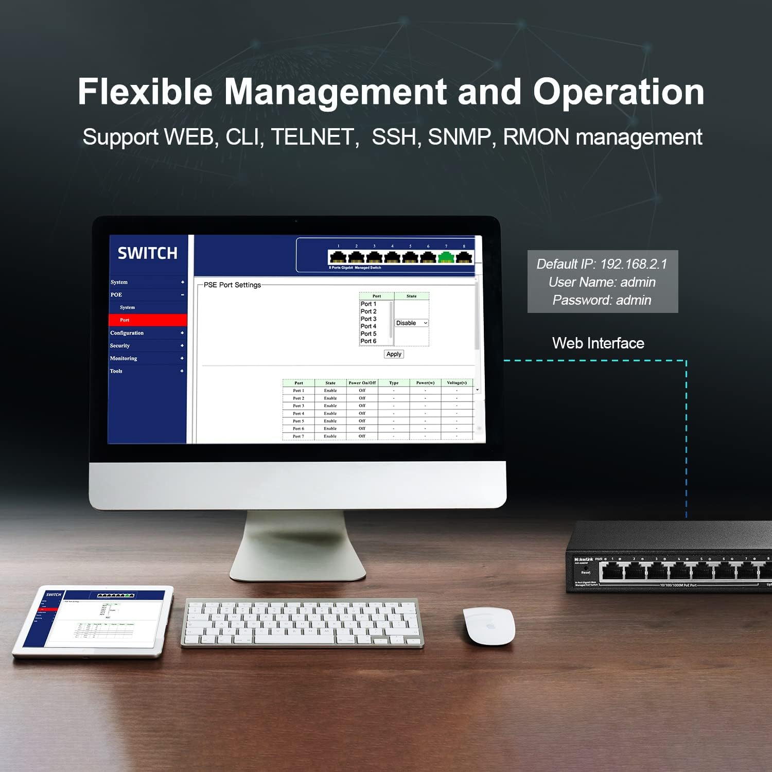
Image: A computer monitor displaying the web-based management interface for the MokerLink switch. The interface shows options for System, PoE, Configuration, Security, Monitoring, and Tools. Default login credentials (IP: 192.168.2.1, User: admin, Password: admin) are also displayed.
6.2 L2 Managed Features
Die web interface provides access to various Layer 2 management functions:
- VLAN's: Skep virtuele plaaslike area netwerke om netwerkverkeer te segmenteer.
- QoS (kwaliteit van diens): Prioritiseer netwerkverkeer vir kritieke toepassings.
- IGMP: Manage multicast traffic.
- Skakel-aggregasie (LACP): Kombineer verskeie fisiese skakels in 'n enkele logiese skakel vir verhoogde bandwydte en oortolligheid.
- Loop Protection (RSTP): Prevent network loops.
- Poortspieëling: Monitor netwerkverkeer deur 'n kopie van pakkies van een poort na 'n ander te stuur.
- Poortisolasie: Isolate ports to prevent communication between them.
- Bandwydtebeheer: Manage bandwidth usage per port.
- MAC-adrestabel: View and manage MAC address entries.
- Uitsaai stormbeheer: Prevent network performance degradation due to excessive broadcast traffic.
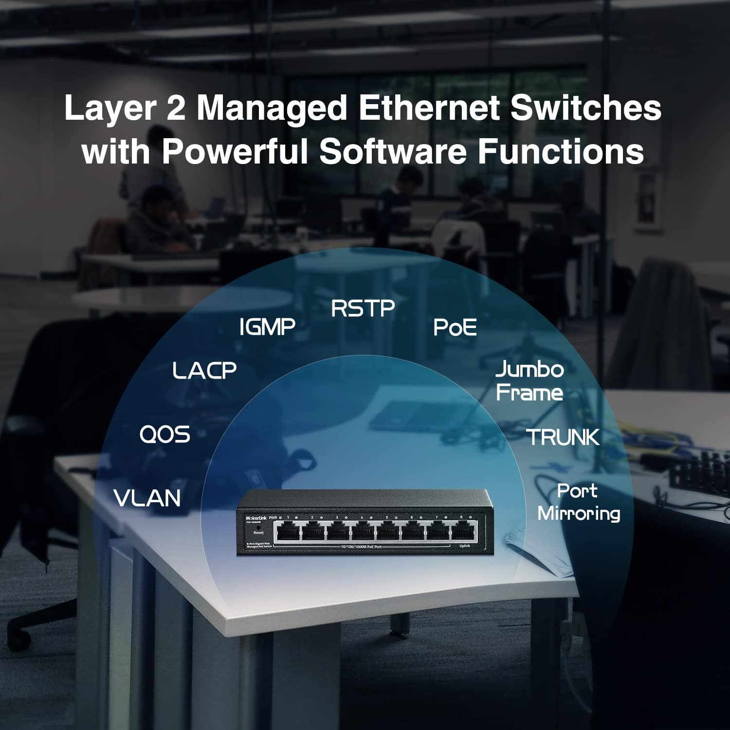
Image: A conceptual diagram showing the various Layer 2 managed features supported by the MokerLink switch, including VLAN, QoS, IGMP, LACP, RSTP, PoE, Jumbo Frame, TRUNK, and Port Mirroring, arranged around an image of the switch.
7. Onderhoud
7.1 Skoonmaak
Regularly clean the exterior of the switch with a soft, dry cloth. Do not use liquid or aerosol cleaners, as they may damage the device.
7.2 Firmware-opdaterings
Check the MokerLink official website periodically for firmware updates. Keeping your device's firmware up-to-date ensures optimal performance, security, and access to new features. Follow the instructions provided with the firmware update package carefully.
7.3 Fabrieksterugstelling
If you encounter persistent issues or forget your login credentials, you can restore the switch to its factory default settings. To perform a factory reset, press and hold the Stel terug button on the front panel for approximately 5-10 seconds until the LEDs flash, then release. The switch will reboot with default settings.
8. Probleemoplossing
- Geen krag: Ensure the power adapter is securely connected to both the switch and a working power outlet. Check the PWR LED. If it's off, try a different outlet or power adapter.
- Geen skakel/aktiwiteit op poort: Verify that the Ethernet cable is properly connected to both the switch port and the connected device. Check the cable for damage. Ensure the connected device is powered on and functioning correctly.
- PoE-toestel ontvang nie krag nie: Confirm that the connected device is IEEE 802.3af/at compliant. Passive 24V PoE and non-PoE devices will not receive power. Check the PoE power budget in the web interface to ensure sufficient power is available.
- Kan nie toegang kry nie Web Interface: Ensure your computer's IP address is in the same subnet as the switch's default IP (192.168.2.x, where x is not 1). Verify the physical connection. Try clearing your browser's cache or using a different browser. If the password was changed and forgotten, perform a factory reset.
- Stadige netwerkprestasie: Check for excessive network traffic or loops. Utilize L2 managed features like bandwidth control or loop protection if configured. Ensure all cables are Gigabit-rated.
9. Spesifikasies
| Kenmerk | Beskrywing |
|---|---|
| Modelnommer | 8 Gigabit PoE(Managed) |
| Aantal poorte | 8 (7 Gigabit PoE, 1 Gigabit Uplink) |
| PoE Standaard | IEEE 802.3af / at |
| Maksimum PoE-krag per poort | 30 W |
| Totale PoE-kragbegroting | 96 W |
| Skakelkapasiteit | 16 Gbps |
| Data-oordragtempo | 16 Gigabit per sekonde |
| Tipe bestuur | L2 Smart Managed (Web GUI, VLAN, QoS, IGMP, LACP, etc.) |
| Materiaal van die saak | Metaal |
| Fanless Design | Ja |
| Kragtoevoer | Eksterne kragadapter (96W) |
| Voltage | 48 Volt |
| Item gewig | 1.8 pond |
| Pakket afmetings | 9.76 x 7.64 x 2.44 duim |
10. Waarborg en Ondersteuning
MokerLink products come with a standard manufacturer's warranty. For detailed warranty information, technical support, or service inquiries, please refer to the warranty card included in your package or visit the official MokerLink website. You can also contact MokerLink customer service directly for assistance.
MokerLink Official Webwebwerf: Visit MokerLink Store on Amazon