1. Veiligheidsinligting
Please read and understand all safety information and operating instructions before using this multimeter. Failure to follow these instructions may result in electric shock, fire, or damage to the meter.
- Maak altyd seker dat die toetsdrade behoorlik gekoppel is en dat die funksieskakelaar op die korrekte reeks gestel is voordat enige metings gemaak word.
- Moenie probeer om voltages or currents exceeding the maximum rated values for this meter.
- Wees uiters versigtig wanneer u met lewendige stroombane werk. Hoë volumetages can be dangerous.
- Never open the meter casing unless specifically instructed for battery or fuse replacement. Ensure test leads are disconnected before opening.
- Vervang die battery wanneer die lae battery-aanwyser verskyn om akkurate lesings te verseker.
- Moenie die meter gebruik as dit beskadig lyk of as die isolasie op die toetsdrade gekompromitteer is nie.
Figuur 1: Agter view of the Rebel MIE-RB-830 Multimeter, showing the battery compartment cover and a warning label. The label advises removing test leads before opening the case to avoid electrical shock and to install fuses with correct amp/volt ratings. It also indicates the power supply is a 9V battery, type NEDA 1604 9V 6F22.
2. Produk verbyview
The Rebel MIE-RB-830 is a compact, battery-operated digital multimeter designed for measuring DC/AC voltage, DC current, resistance, diode, and transistor (hFE) values. It is suitable for general electrical testing and troubleshooting.
2.1. Komponente
- Digital Multimeter Unit
- Toetsdrade (Rooi en Swart)
- 9V Battery (may be included or sold separately)
- Gebruikershandleiding (hierdie dokument)

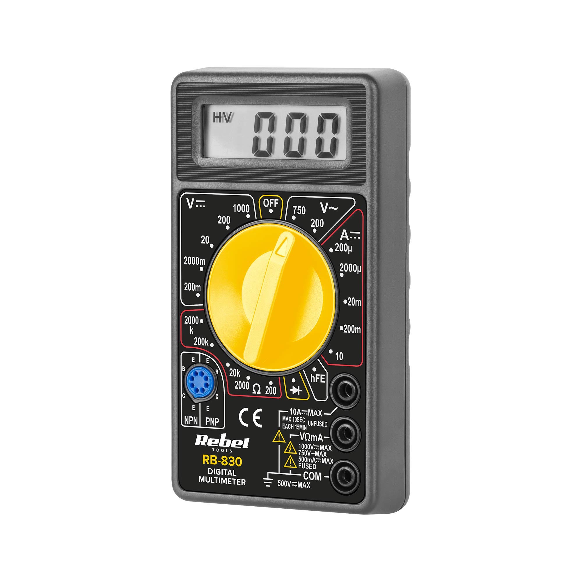
Figuur 2: The Rebel MIE-RB-830 Digital Multimeter shown with its accompanying red and black test leads. The multimeter features a large LCD display and a rotary function switch.

Figuur 3: Close-up view of the red and black test leads. These leads are essential for connecting the multimeter to the circuit under test.
3. Opstelling
3.1. Battery Installasie
- Maak seker dat die multimeter AFGESKAKEL is en dat alle toetsdrade ontkoppel is.
- Locate the battery compartment cover on the back of the meter (refer to Figure 1).
- Draai die bevestigingsskroef(e) los en verwyder die deksel versigtig.
- Insert a new 9V battery (NEDA 1604 or 6F22 type), observing the correct polarity (+ and -).
- Plaas die batteryklepdeksel terug en maak dit vas met die skroef(e).
3.2. Verbinding van toetsdrade
- Koppel die rooi test lead to the "VΩmA" input jack.
- Koppel die swart test lead to the "COM" (common) input jack.
- For current measurements exceeding 200mA (up to 10A), connect the red test lead to the "10A" input jack.
4. Bedryfsinstruksies
4.1. Funksie Keuse
Turn the rotary switch to the desired measurement function and range. Always start with a higher range if the approximate value is unknown to prevent overloading the meter.
4.2. Meting van GS-volumetage (V–)
- Stel die draaiskakelaar op die verlangde GS-volumetage (V–) range (e.g., 20V, 200V).
- Verbind die rooi toetsdraad aan die positiewe (+) kant van die stroombaan en die swart toetsdraad aan die negatiewe (-) kant.
- Lees die voltage -waarde op die LCD -skerm.
4.3. Meet AC Voltage (V∼)
- Stel die draaiskakelaar op die verlangde WS-volumetage (V∼) range (e.g., 200V, 750V).
- Verbind die toetsdrade oor die WS-volumetage bron.
- Lees die voltage -waarde op die LCD -skerm.
4.4. Measuring DC Current (A–)
Waarskuwing: To measure current, the meter must be connected in series with the circuit. Never connect the meter in parallel with a voltagdie bron wanneer in stroommodus, aangesien dit die meter en stroombaan kan beskadig.
- Set the rotary switch to the desired DC Current (A–) range (e.g., 20mA, 200mA, 10A).
- For currents up to 200mA, ensure the red lead is in the "VΩmA" jack. For currents up to 10A, move the red lead to the "10A" jack.
- Maak die stroombaan oop waar die stroom gemeet moet word en koppel die meter in serie.
- Lees die huidige waarde op die LCD-skerm.
4.5. Meting van weerstand (Ω)
Waarskuwing: Ensure the circuit or component under test is de-energized before measuring resistance.
- Set the rotary switch to the desired Resistance (Ω) range (e.g., 200Ω, 2kΩ, 200kΩ).
- Verbind die toetsdrade oor die komponent of stroombaan wat gemeet moet word.
- Lees die weerstandswaarde op die LCD-skerm.
4.6. Diode Test (→|–)
- Set the rotary switch to the Diode Test (→|–) position.
- Connect the red test lead to the anode of the diode and the black test lead to the cathode.
- Die skerm sal die vorentoe volume wystage drop (typically 0.5V to 0.8V for silicon diodes).
- Reverse the leads. The display should show "OL" (Open Loop) for a good diode.
4.7. Transistor (hFE) Toets
- Stel die draaiskakelaar na die hFE-posisie.
- Identifiseer of die transistor NPN of PNP is.
- Insert the transistor's emitter, base, and collector leads into the corresponding sockets on the hFE test socket.
- Read the hFE (DC current gain) value on the display.
5. Onderhoud
5.1. Battery vervanging
When the low battery indicator appears on the display, replace the 9V battery as described in Section 3.1. Using a low battery can lead to inaccurate readings.
5.2. Sekering vervanging
If the current measurement function stops working, the fuse may need replacement. This operation should only be performed by qualified personnel.
- Maak seker dat die multimeter AFGESKAKEL is en dat alle toetsdrade ontkoppel is.
- Open the back casing of the meter (this may involve more screws than just the battery compartment).
- Locate the blown fuse and replace it with a fuse of the exact same type and rating (e.g., F200mA/250V for mA range, F10A/250V for 10A range). Refer to the internal markings or specifications for precise fuse ratings.
- Sit die meter versigtig weer aanmekaar en maak seker dat alle skroewe vasgedraai is.
5.3. Skoonmaak
Vee die meter met advertensie afamp lap en sagte skoonmaakmiddel. Moenie skuurmiddels of oplosmiddels gebruik nie. Hou die meter droog.
6. Probleemoplossing
| Probleem | Moontlike oorsaak | Oplossing |
|---|---|---|
| Geen vertoon of dowwe vertoon | Lae of dooie battery | Vervang die 9V-battery. |
| Verkeerde lesings | Low battery; Incorrect range selection; Poor test lead connection | Replace battery; Select appropriate range; Ensure leads are firmly connected. |
| Stroommeting werk nie | Blown fuse; Incorrect lead connection for current | Replace fuse (see Section 5.2); Ensure red lead is in "VΩmA" or "10A" jack as appropriate. |
| "OL" (Oorlading) word vertoon | Measured value exceeds selected range; Open circuit (for resistance/continuity) | Select a higher range; Check circuit for breaks. |
7. Spesifikasies
| Metingsfunksie | Reeks | Akkuraatheid |
|---|---|---|
| DC Voltage (V–) | 200mV, 2V, 20V, 200V, 1000V | ±(0.5% + 2 syfers) |
| AC Voltage (V∼) | 200V, 750V | ±(1.2% + 10 syfers) |
| DC Current (A–) | 200µA, 2mA, 20mA, 200mA, 10A | ±(1.0% + 2 syfers) |
| Weerstand (Ω) | 200Ω, 2kΩ, 20kΩ, 200kΩ, 2MΩ | ±(0.8% + 2 syfers) |
| Diodetoets | Ja | Voorwaarts voltage druppel |
| Transistor (hFE) Toets | Ja | hFE value |
| Kragtoevoer | 9V Battery (NEDA 1604 or 6F22) | |
| Vertoon | 3½ Digit LCD, Max. 1999 | |
| Afmetings | Ongeveer 13.5 x 10 x 4 cm | |
| Gewig | Approx. 107 grams (without battery) | |
| Bedryfstemperatuur | 0°C tot 40°C (32°F tot 104°F) | |
| Bergingstemperatuur | -10°C tot 50°C (14°F tot 122°F) | |
| Veiligheidstandaarde | CE, RoHS |
8. Waarborg en Ondersteuning
This Rebel MIE-RB-830 Digital Multimeter is covered by a standard manufacturer's warranty against defects in materials and workmanship. Please refer to the warranty card included with your purchase or contact your retailer for specific warranty terms and conditions.
For technical support or service inquiries, please contact the point of purchase or visit the official Rebel webwebwerf vir kontakinligting.