GVDA GD128
GVDA GD128 Digitale Multimeter Gebruikershandleiding
Model: GD128
Handelsmerk: GVDA
1. Inleiding
The GVDA GD128 SMART Digital Multimeter is a professional testing instrument designed for accurate and reliable measurements. It is an ideal choice for professional electricians, engineers, electronics enthusiasts, and for general household use. This manual provides detailed instructions on the safe and effective operation of your GD128 multimeter.
Sleutelvermoëns sluit in:
- AC en DC Voltage Meting
- WS- en GS-stroommeting
- Weerstandmeting
- Kapasitansiemeting
- Kontinuïteitsmeting
- Diode-meting
- NCV (Nie-Kontak Voltage) Meting
- True RMS for accurate readings of non-sinusoidal signals
- Large VA color HD LCD screen with 9999 counts display
- Outomatiese en handmatige wissel
- Flashlight and Input Connector LED Indication

Figure 1.1: GVDA GD128 Digital Multimeter with test probes.
2. Veiligheidsinligting
WARNING: To avoid electrical shock or personal injury, please read and understand all instructions and safety information before using this multimeter.
- Always ensure the multimeter is in the correct function and range before making measurements.
- Moenie die maksimum invoerwaardes vir enige reeks oorskry nie.
- Wees versigtig wanneer u met voltagbo 30V AC RMS, 42V piek, of 60V DC. Hierdie volumestagdit hou 'n skokgevaar in.
- Inspekteer toetsdrade vir beskadigde isolasie of blootgestelde metaal voor gebruik. Vervang indien beskadig.
- Do not operate the multimeter if it appears damaged or if it is not operating properly.
- Ontkoppel altyd die krag na die stroombaan en ontlaai alle hoëvolume.tage kapasitors voordat weerstand, kontinuïteit, diodes of kapasitansie getoets word.
- Maak seker dat die batteryklep stewig toe is voor gebruik.
- This device meets safety standards EN61010-1,-2-030, EN61010-2-033, EN61326-1 CAT III 1000V, CAT IV 600V.
3. Produk verbyview en komponente
Familiarize yourself with the different parts of your GVDA GD128 Digital Multimeter.

Figuur 3.1: Voor- en sykant view of the GD128 Multimeter with labeled components.
- NCV Sensor area
- Aan / uit-sleutel
- Flitslig sleutel
- Waarskuwingsaanwyser
- Flitslig
- Invoeraansluiting-aanwyser
- Jack other than current and NCV
- COM jack (Common)
- mA (<600mA) jack
- 10A domkrag
- Auto power off key
- Funksie sleutel
- Vertoon

Figuur 3.2: Agter view of the GD128 Multimeter highlighting the integrated LED flashlight.
4. Opstelling
4.1 Battery installasie
The GVDA GD128 Multimeter requires 3 x 1.5V AAA batteries (not included) for operation.
- Maak seker dat die multimeter afgeskakel is.
- Vind die batterykompartement aan die agterkant van die toestel.
- Gebruik 'n skroewedraaier om die batteryklepdeksel oop te maak.
- Plaas 3 AAA-batterye in en let op die korrekte polariteit (+ en -) soos aangedui in die kompartement.
- Plaas die deksel van die batterykompartement terug en maak dit met die skroef vas.
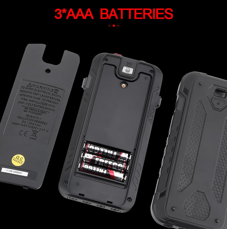
Figuur 4.1: Batterykompartement vir 3 AAA-batterye.
4.2 Verbinding van toetsdrade
Connect the test leads to the appropriate input jacks for the desired measurement function. Always connect the black test lead to the COM (Common) jack. Connect the red test lead to the jack corresponding to the measurement type (e.g., VΩHz for voltage/resistance/frequency, mA for milliampere current, 10A for ampere current).
5. Bedryfsinstruksies
The GD128 features both auto-ranging and manual-ranging capabilities. The "SMART" function automatically identifies AC/DC voltage, weerstand en kontinuïteit.
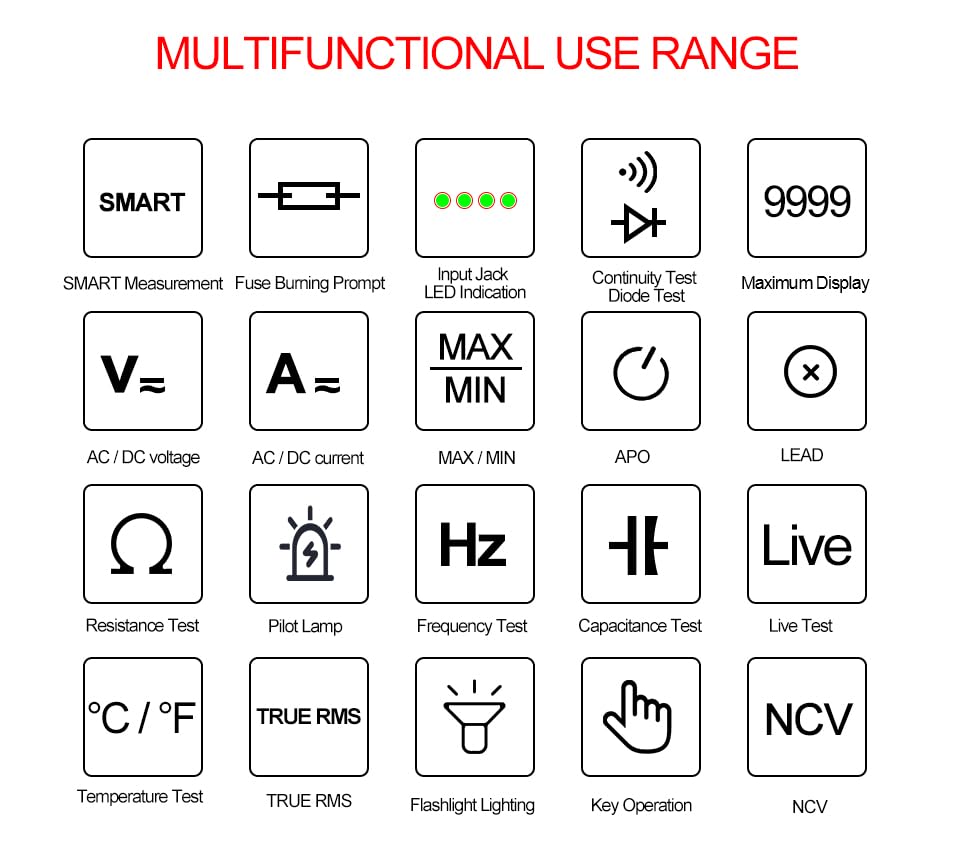
Figure 5.1: Multifunctional Use Range icons.
5.1 Krag aan/af
Druk die Aan / uit-sleutel (2) to turn the multimeter on or off.
5.2 Funksiekeuse
The multimeter typically starts in SMART mode. Press the FUNC (Function) key (12) or SEL key to cycle through different measurement modes within a category (e.g., AC/DC voltage, weerstand/kontinuïteit/diode).
5.3 Common Measurement Functions
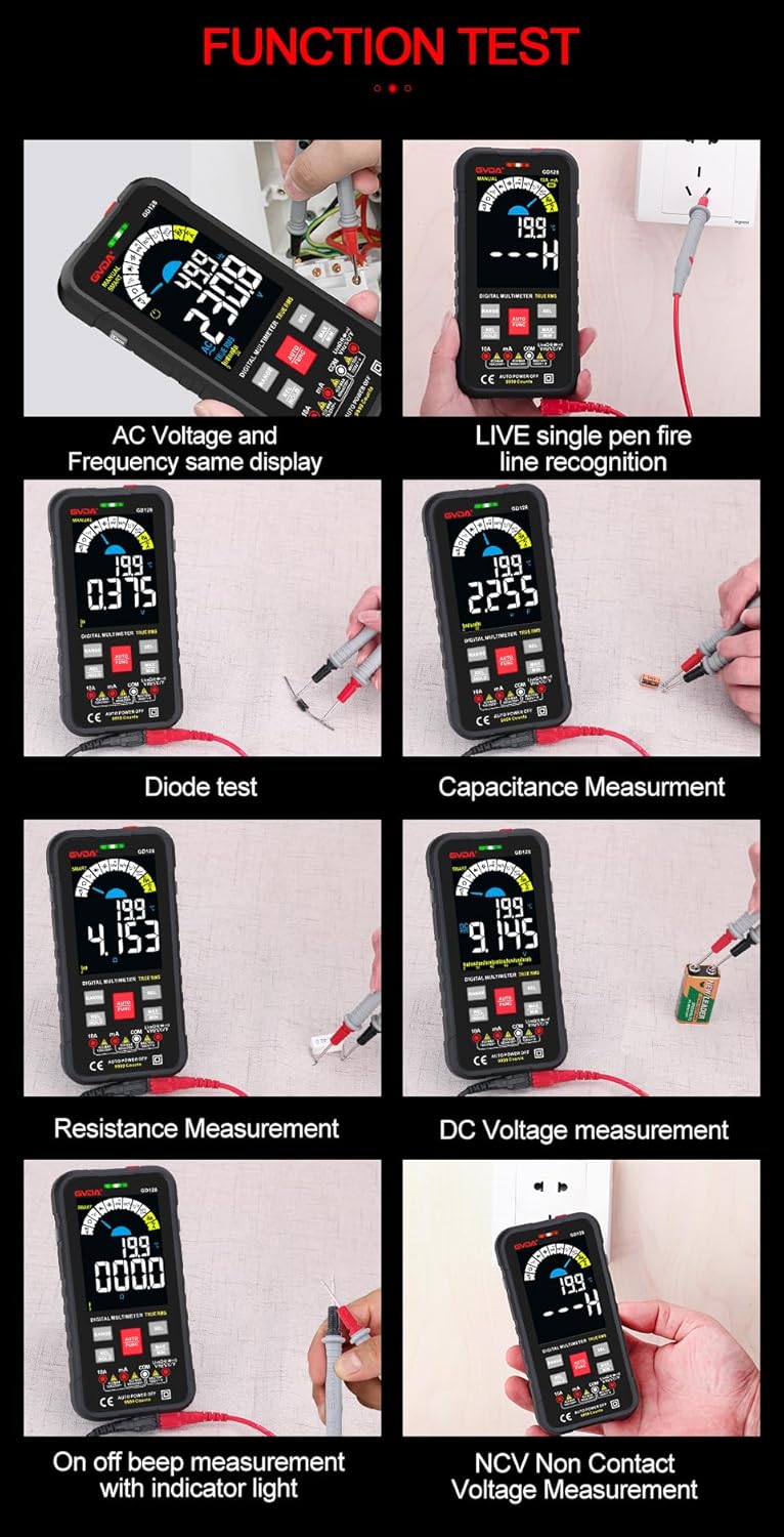
Figuur 5.2: Examples of various function tests.
5.3.1 Vlugtage Meting (WS/GS)
- Connect the black test lead to the COM jack and the red test lead to the VΩHz jack.
- Select the appropriate AC (~) or DC (---) voltage modus.
- Koppel die toetsdrade parallel aan die stroombaan of komponent wat gemeet moet word.
- Die skerm sal die voltage lees.
5.3.2 Stroommeting (WS/GS)
- Koppel die swart toetskabel aan die COM-aansluiting.
- For current up to 600mA, connect the red test lead to the mA jack. For current up to 10A, connect the red test lead to the 10A jack.
- Select the appropriate AC (~) or DC (---) current mode.
- Verbind die multimeter in serie met die stroombaan wat gemeet moet word.
- Die skerm sal die huidige lesing wys.
5.3.3 Weerstandsmeting (Ω)
- Connect the black test lead to the COM jack and the red test lead to the VΩHz jack.
- Select the Resistance (Ω) mode.
- Maak seker dat die stroombaan gedeaktiveer is voordat weerstand gemeet word.
- Verbind die toetsdrade oor die komponent wat gemeet moet word.
- Die skerm sal die weerstandslesing wys.
5.3.4 Capacitance Measurement (F)
- Connect the black test lead to the COM jack and the red test lead to the VΩHz jack.
- Select the Capacitance (F) mode.
- Ensure the capacitor is fully discharged before measurement to avoid damage to the multimeter.
- Verbind die toetsdrade oor die kondensatorterminale.
- Die skerm sal die kapasitansielesing wys.
5.3.5 Kontinuïteitstoets (Ω)
- Connect the black test lead to the COM jack and the red test lead to the VΩHz jack.
- Select the Continuity mode.
- Touch the test leads to the points you want to check for continuity. A continuous beep indicates a complete circuit.
5.3.6 Diodetoets (→|)
- Connect the black test lead to the COM jack and the red test lead to the VΩHz jack.
- Select the Diode Test mode.
- Connect the red test lead to the anode and the black test lead to the cathode of the diode. The display will show the forward voltage drop. Reverse the leads; an open circuit (OL) reading indicates a good diode.
5.3.7 NCV (Nie-kontakvolume)tage) Meting
- Kies die NCV-modus.
- Move the NCV sensor area (1) near the conductor. The multimeter will beep and the warning indicator (4) will light up with increasing frequency as it detects AC voltage.
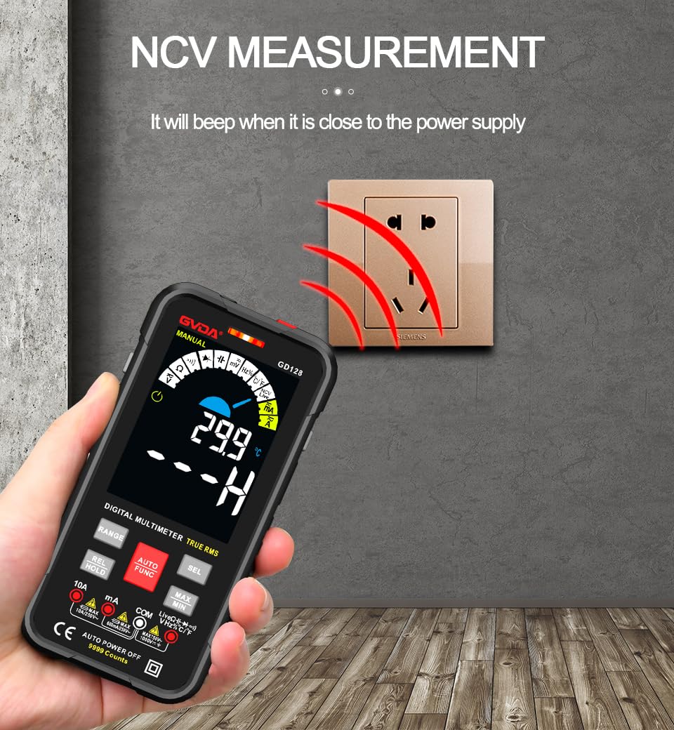
Figure 5.3: NCV (Non-Contact Voltage) measurement in progress.
5.3.8 Ander funksies
- Ware RMS: Verskaf akkurate lesings vir beide sinusvormige en nie-sinusvormige WS-golfvorms.
- MAX/MIN/AVG: Druk die MAX/MIN key to record maximum, minimum, and average readings.
- REL (Relatiewe Meting): Druk die REL/HOUD key briefly to set the current reading as a reference for subsequent measurements.
- Datahou: Druk die REL/HOUD key briefly to freeze the current reading on the display.
- Flitslig: Druk die Flitslig sleutel (3) to turn the built-in flashlight on/off.
- Outomatiese Afskakeling (APO): The multimeter will automatically power off after a period of inactivity to save battery life.
6. Aansoeke
The GVDA GD128 Digital Multimeter is versatile and suitable for a wide range of applications, including but not limited to:

Figure 6.1: Diverse applications of the GD128 Multimeter.
- Electronic beginners and hobbyists
- Electronic circuit installation and testing
- Electronic maintenance and repair
- Electromechanical maintenance
- Vehicle inspection and automotive electrical work
- Maintenance of household appliances
- General electrical troubleshooting
7. Spesifikasies
Detailed technical specifications for the GVDA GD128 Digital Multimeter:
| Kenmerk | Reeks | Presisie |
|---|---|---|
| DC Voltage | 99.99mV/999.9mV; 9.999V/99.9V/1000V | ±(0.5%+3) |
| AC Voltage | 99.9mV/999.9/mV; 9.999V/99.9V/750V | ±(0.8%+3) |
| DC Stroom | 9.999mA/99.99mA/999.9mA; 9.99A | ±(0.8%+3) for mA, ±(1.2%+3) for A |
| WS-stroom | 9.999mA/99.99mA/999.9mA; 9.99A | ±(1.0%+3) for mA, ±(1.5%+3) for A |
| Weerstand | 99.99/999.9 ohms/9.999k/99.99k/999.9kohm; 9.999 m/99.99 m ohms | ±(0.8%+3) for kΩ, ±(1.2%+3) for MΩ |
| Kapasitansie | 9.999/99.99/999.9nF/9.999/99.99/999.9uF; 9.999mF/99.99mF | ±(4.0%+3) vir nF/uF, ±(5.0%+5) vir mF |
| Frekwensie | 99.99/999.9/9.999k/99.99k/999.9kHz/9.999mHz | ±(1.0%+3) |
| Pligsiklus | 0.1%-99.99% | ±(1.0%+2) |
| Temperatuur | -40~1000°C; -40-1832°F | ±2°C |
| Vertoon telling | 9999 tellings | |
| Tipe vertoon | VA color screen | |
| Sampling Koers | Ongeveer. 3 keer per sekonde | |
| Oor-reeks vertoon | "OL" | |
| Lae Voltage Aanduiding | Lae battery aanduiding | |
| Kragtoevoer | 3 x 1.5V AAA-batterye (nie ingesluit nie) | |
| Produk Gewig | Ongeveer. 230g | |
| Produk Grootte | 83 x 23 x 165 mm | |
| Veiligheidsgradering | EN61010-1,-2-030 EN61010-2-033, EN61326-1 CAT III 1000 V CAT IV 600 V |
8. Onderhoud
Behoorlike onderhoud verseker die lang lewensduur en akkuraatheid van jou multimeter.
- Skoonmaak: Vee die omhulsel af met advertensieamp lap en sagte skoonmaakmiddel. Moenie skuurmiddels of oplosmiddels gebruik nie.
- Battery vervanging: Vervang batterye dadelik wanneer die lae battery-aanwyser verskyn om akkurate lesings te verseker.
- Sekering vervanging: If the current measurement function fails, the fuse may be blown. Refer to the warning label inside the battery compartment for fuse specifications (e.g., F600mA/250V, F10A/250V). Ensure the multimeter is off and test leads are disconnected before replacing fuses.
- Berging: If the multimeter is not used for a long period, remove the batteries to prevent leakage. Store in a cool, dry place away from direct sunlight.
9. Probleemoplossing
If you encounter issues with your GVDA GD128 Multimeter, try the following:
- Geen skerm/aanskakel: Kontroleer batteryinstallasie en maak seker dat batterye nie leeg is nie. Vervang indien nodig.
- Verkeerde lesings: Verify test lead connections, ensure the correct function and range are selected, and check if the circuit is de-energized for resistance/continuity/capacitance tests.
- "OL" Vertoon: Indicates an over-range condition or an open circuit (e.g., when measuring resistance on an open wire).
- Geen kontinuïteitspieptoon: Check if the circuit is truly continuous. If not, the circuit is open.
- Fuse Blown Warning: If the current measurement function is not working, the fuse might be blown. Replace the fuse as per maintenance instructions.
Vir aanhoudende probleme, kontak kliëntediens.
10. Waarborg en Ondersteuning
Your GVDA GD128 Digital Multimeter comes with a 30-dae waarborg for system failures or factory problems. Please retain your proof of purchase for warranty claims.
For technical support, warranty claims, or further assistance, please refer to the contact information provided with your product packaging or visit the official GVDA webwebwerf.
11. Pakketinhoud
Upon opening your GVDA GD128 Digital Multimeter package, you should find the following items:

Figure 11.1: Contents included in the GD128 Multimeter package.
- 1 x GVDA GD128 Digital Multimeter
- 1 x Test Lead Set (Original pen cable)
- 1 x lap sak
- 1 x Termokoppel-sonde
- 1 x Gebruikershandleiding
- 1 x Gift Box (Packaging)
Ask a question about this manual
Ask about setup, troubleshooting, compatibility, parts, safety, or missing instructions. Manuals+ will review the question and use this page’s manual context to help answer it.