1. Inleiding
This manual provides essential instructions for the safe and effective use of your DT321B Digital Multimeter. This portable device is designed for measuring AC/DC voltage, DC current, resistance, and includes features for diode testing, continuity, battery testing, and transistor (hFE) measurements. Please read this manual thoroughly before operation and retain it for future reference.
2. Veiligheidsinligting
Always observe basic safety precautions when using this multimeter to reduce the risk of fire, electric shock, or personal injury.
- Moenie toepas voltage or current that exceeds the maximum specified limits for the multimeter.
- Maak seker dat die toetsdrade in 'n goeie toestand en behoorlik gekoppel is voordat enige metings gemaak word.
- Never use the multimeter if it appears damaged or if the test leads are damaged.
- Wees versigtig wanneer jy met vol werktagbo 30V AC RMS, 42V piek, of 60V DC. Hierdie volumestagdit hou 'n skokgevaar in.
- Ontkoppel altyd die krag na die stroombaan wat getoets word voordat u weerstand of kontinuïteit meet.
- Do not operate the multimeter in explosive atmospheres.
- Vervang batterye wanneer die lae battery-aanwyser verskyn om akkurate lesings te verseker.
3. Produk verbyview
The DT321B Digital Multimeter features a clear LCD display and a rotary switch for selecting various measurement functions. Input jacks are provided for connecting test leads.

Figuur 3.1: Voorkant view of the DT321B Digital Multimeter with key components labeled. The display shows numerical readings, the hold button freezes the current reading, and the rotary switch selects measurement functions. The '10A' jack is for high current measurements, 'COM' is the common ground, and 'VΩmA' is for voltage, weerstand en lae stroommetings.
The multimeter includes a blue backlight for improved visibility in low-light conditions and a data hold function to freeze the displayed reading.
4. Opstelling
4.1 Battery installasie
The DT321B Digital Multimeter requires two 1.5V batteries (Type 7, typically AAA) for operation. To install or replace batteries:
- Maak seker dat die multimeter AFGESKAKEL is.
- Vind die batteryklepdeksel aan die agterkant van die eenheid.
- Draai die bevestigingsskroef(e) los en verwyder die deksel.
- Insert the two 1.5V batteries, observing the correct polarity (+ and -) as indicated inside the compartment.
- Plaas die batteryklepdeksel terug en maak dit vas met die skroef(e).
5. Bedryfsinstruksies
Before making any measurements, ensure the test leads are securely plugged into the correct input jacks.

Figure 5.1: The DT321B Multimeter with test probes connected. The black probe is connected to the 'COM' (common) jack, and the red probe is connected to the 'VΩmA' jack for most voltage, weerstand en lae stroommetings.
5.1 Meet DC Voltage (V–)
- Steek die rooi toetsdraad in die 'VΩmA'-aansluiting en die swart toetsdraad in die 'COM'-aansluiting.
- Stel die draaiskakelaar op die verlangde GS-volumetage (V–) range (e.g., 200m, 2, 20, 200, 1000V). If the voltage is unknown, start with the highest range and work downwards.
- Koppel die toetsprobes oor die komponent of stroombaan wat gemeet moet word.
- Lees die voltage -waarde op die LCD -skerm.
5.2 Meting van AC Voltage (V∼)
- Steek die rooi toetsdraad in die 'VΩmA'-aansluiting en die swart toetsdraad in die 'COM'-aansluiting.
- Stel die draaiskakelaar op die verlangde WS-volumetage (V∼) range (e.g., 200, 750V).
- Koppel die toetsprobes oor die komponent of stroombaan wat gemeet moet word.
- Lees die voltage -waarde op die LCD -skerm.
5.3 Meting van GS-stroom (A–)
WAARSKUWING: To avoid damage to the multimeter or the circuit, never connect the test leads in parallel across a voltage source when measuring current. Always connect in series.
- For currents up to 200mA, insert the red test lead into the 'VΩmA' jack. For currents up to 10A, insert the red test lead into the '10A MAX' jack. The black test lead always goes into the 'COM' jack.
- Set the rotary switch to the desired DC Current (A–) range (e.g., 200u, 2m, 20m, 200m, 10A).
- Open the circuit where current is to be measured and connect the multimeter in series with the circuit.
- Lees die huidige waarde op die LCD-skerm.
5.4 Meting van Weerstand (Ω)
WAARSKUWING: Ensure the circuit under test is completely de-energized before measuring resistance.
- Steek die rooi toetsdraad in die 'VΩmA'-aansluiting en die swart toetsdraad in die 'COM'-aansluiting.
- Set the rotary switch to the desired Resistance (Ω) range (e.g., 200, 2k, 20k, 200k, 2M).
- Verbind die toetsprobes oor die komponent wat gemeet moet word.
- Lees die weerstandswaarde op die LCD-skerm.
5.5 Diode-toets
- Steek die rooi toetsdraad in die 'VΩmA'-aansluiting en die swart toetsdraad in die 'COM'-aansluiting.
- Set the rotary switch to the diode symbol (→|).
- Verbind die rooi sonde aan die anode en die swart sonde aan die katode van die diode. Die skerm sal die voorwaartse volume wys.tage druppel.
- Reverse the probes. The display should show 'OL' (open loop) for a good diode.
5.6 Kontinuïteitstoets
- Steek die rooi toetsdraad in die 'VΩmA'-aansluiting en die swart toetsdraad in die 'COM'-aansluiting.
- Stel die draaiskakelaar op die kontinuïteitsimbool (♫).
- Connect the test probes across the circuit or component. If continuity exists (resistance below a certain threshold), the buzzer will sound.
5.7 Battery Testing (1.5V / 9V)
- Steek die rooi toetsdraad in die 'VΩmA'-aansluiting en die swart toetsdraad in die 'COM'-aansluiting.
- Set the rotary switch to the '1.5V BATT' or '9V BATT' position.
- Verbind die rooi sonde aan die positiewe terminaal en die swart sonde aan die negatiewe terminaal van die battery.
- Lees die battery voltage op die skerm.
5.8 Transistor (hFE) Test
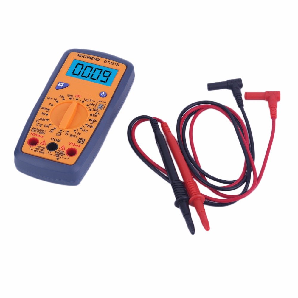
Figure 5.2: The DT321B Multimeter in use, with an inset showing a transistor being tested. The multimeter can measure the hFE (current gain) of NPN and PNP transistors.
- Set the rotary switch to the 'hFE' position.
- Identify the NPN or PNP type of the transistor.
- Insert the transistor leads (Emitter, Base, Collector) into the corresponding sockets in the 'hFE' test socket on the multimeter.
- Lees die hFE-waarde op die LCD-skerm.
5.9 Data Vashou Funksie
Press the 'Hold' button to freeze the current reading on the display. Press it again to release the hold function and resume live readings.
5.10 Agtergrondbeligtingsfunksie
The multimeter features a blue backlight. Press the backlight button (often integrated with the 'Hold' button or a separate button with a light symbol) to turn the backlight on or off for improved visibility.
6. Onderhoud
6.1 Skoonmaak
Vee die omhulsel af met advertensieamp cloth and a mild detergent. Do not use abrasives or solvents. Ensure the multimeter is completely dry before use.
6.2 Batteryvervanging
When the low battery symbol appears on the display, replace the batteries as described in Section 4.1. Remove batteries if the multimeter is not used for extended periods to prevent leakage.
7. Probleemoplossing
- Geen vertoon of dowwe vertoon: Kontroleer batteryinstallasie en laai. Vervang batterye indien nodig.
- Verkeerde lesings: Ensure the rotary switch is set to the correct function and range. Check test lead connections. Verify the circuit under test is properly prepared (e.g., de-energized for resistance).
- 'OL' (Oorlading) word vertoon: The measured value exceeds the selected range. Switch to a higher range or check for an open circuit.
- No continuity buzzer: Ensure the multimeter is in continuity mode and the circuit is closed.
8. Spesifikasies
| Meting | Reeks | Akkuraatheid |
|---|---|---|
| DC Voltage | 200mV, 2V, 20V, 200V, 1000V | ±0.5% |
| AC Voltage | 200V, 750V | ±1.0% |
| DC Stroom | 200uA, 2mA, 20mA, 200mA, 10A | ±1.8% |
| Weerstand | 200Ω, 2kΩ, 20kΩ, 200kΩ, 2MΩ | ±1.0% |
Algemene spesifikasies:
- LCD skerm grootte: 45x23 mm
- Produk Grootte: 160 x 76 x 32 mm
- Kragtoevoer: 2 x 1.5V batteries (Type 7 / AAA)
- Lae Voltage Symbol Display: Ja
- Oorladingsbeskerming: Ja
- Diode Detection: Ja
- On-off Detection & Buzzer: Ja
- Batterykapasiteit opsporing: 1.5V / 9V
- Transistor Detection (hFE): Ja
- Databehoud: Ja
- Agterligskerm: Ja
9. Waarborg en Ondersteuning
Specific warranty and support information for the DT321B Digital Multimeter is not available in the provided product details. Please refer to the retailer or manufacturer's website for any applicable warranty terms or customer support contacts.