1. Produk verbyview
The Generic Mini 360 DC-DC Step-Down Power Converter is a compact, non-isolated buck module designed for efficient voltage conversion. It takes a higher DC input voltage and converts it to a lower, adjustable DC output voltage. This module is suitable for various electronic projects requiring a stable and adjustable power supply.
Sleutel kenmerke:
- Module Properties: Non-isolated step-down (BUCK) converter.
- Regstelling: Synchronous rectification for improved efficiency.
- Invoer Voltage reeks: DC 4.75V tot 23V.
- Uitset Voltage reeks: DC 1.0V to 17V (adjustable).
- Uitsetstroom: Rated 1.8A, maximum 3A (not for prolonged use at max).
- Omskakelingsdoeltreffendheid: Up to 96%.
- Skakelfrekwensie: 340 XNUMX XNUMX KHz.
- Uitsetrimpel: 30mV (no-load).
Figuur 1: Bo view of the Mini 360 module, highlighting its compact design and main components.
2. Spesifikasies
| Parameter | Waarde |
|---|---|
| Module tipe | Non-isolated Step-Down (BUCK) |
| Invoer Voltage | GS 4.75V - 23V |
| Uitset Voltage | GS 1.0V - 17V (Verstelbaar) |
| Output Current (Rated) | 1.8A |
| Uitsetstroom (maksimum) | 3A (short duration only) |
| Omskakelingsdoeltreffendheid | Tot 96% |
| Skakelfrekwensie | 340 KHz |
| Uitset Ripple | 30mV (no-load) |
| Montage tipe | PCB Mount |
| Afmetings | (Approximate, based on typical Mini 360 modules) 17mm x 11mm x 3.8mm |
3. Opstelling en verbindings
Before connecting the module, ensure all power sources are disconnected. Observe proper polarity to prevent damage to the module and connected devices.
Verbindingspunte:
- IN+: Positiewe inset voltage verbinding.
- IN-: Negatiewe inset voltage connection (Ground).
- UIT+: Positiewe uitset voltage verbinding.
- OUT-: Negatiewe uitset voltage connection (Ground).

Figuur 2: Onder view of the Mini 360 module, indicating the IN+ (input positive), IN- (input negative), OUT+ (output positive), and OUT- (output negative) terminals.
Installasie stappe:
- Identify the input and output terminals on the module.
- Connect your DC power source (e.g., battery, power adapter) to the IN+ en IN- terminals. Ensure the input voltage is binne die gespesifiseerde reeks van 4.75V tot 23V.
- Connect your load (the device requiring power) to the UIT+ en UIT- terminale.
- Before applying power, double-check all connections for correct polarity and secure contact.

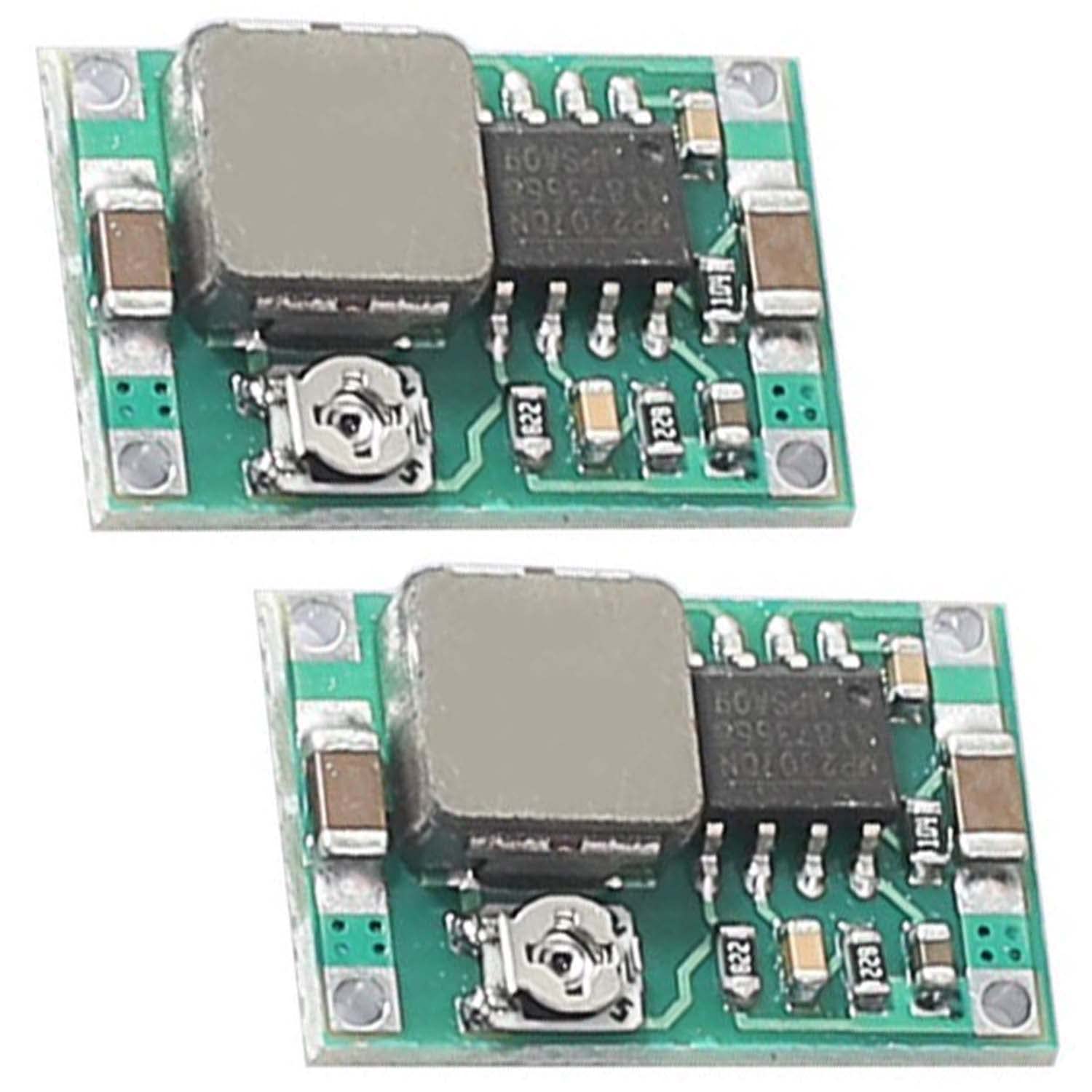
Figure 3: A pair of Mini 360 modules, illustrating their small size and the distinct top and bottom sides for connection.
4. Bedryfsinstruksies
Die uitset voltage of the Mini 360 module is adjustable using the onboard potentiometer.
- With the input power connected and the load disconnected, apply power to the module.
- Gebruik 'n multimeter om die voltage oorkant die UIT+ en UIT- terminale.
- Carefully turn the small screw on the potentiometer (the small metallic component with a screw slot) using a precision screwdriver. Turning clockwise typically increases the voltage, while turning counter-clockwise decreases it.
- Adjust the potentiometer until the desired output voltage (between 1.0V and 17V) is achieved.
- Sodra die gewenste voltage is set, disconnect the input power, then connect your load to the output terminals. Reapply input power.
- Let wel: Do not exceed the maximum output current of 3A, and avoid prolonged operation above 1.8A to ensure module longevity. Ensure the input voltage is always higher than the desired output voltage for proper step-down operation.

Figure 4: A close-up of two Mini 360 modules, highlighting the adjustable potentiometer (silver screw) used for setting the output voltage.
5. Onderhoud
The Mini 360 module is a low-maintenance electronic component. Follow these guidelines to ensure optimal performance and longevity:
- Hou skoon: Ensure the module is free from dust, dirt, and moisture. Use a soft, dry brush or compressed air for cleaning if necessary.
- Omgewingstoestande: Operate the module within its specified temperature range. Avoid extreme heat, cold, or high humidity.
- Vermy oorlading: Do not draw more current than the module's rated capacity (1.8A continuous, 3A peak). Overloading can lead to overheating and permanent damage.
- Veilige verbindings: Periodically check that all input and output connections are secure and free from corrosion.
- Fisiese beskerming: Protect the module from physical impact or bending, which could damage the PCB or components.
6. Probleemoplossing
| Probleem | Moontlike oorsaak | Oplossing |
|---|---|---|
| Geen uitset voltage |
|
|
| Uitset voltage is incorrect or unstable |
|
|
| Module oorverhit |
|
|
7. Waarborg en Ondersteuning
This product is typically sold as a component for DIY electronics projects and may not come with an explicit manufacturer's warranty. For support regarding this product, please refer to the retailer or seller from whom it was purchased. Ensure you retain your proof of purchase for any potential inquiries.
For technical assistance, online communities and forums dedicated to electronics and DIY projects can be valuable resources for troubleshooting and application advice.