1. Inleiding
This user manual provides essential information for the safe and efficient installation, operation, and maintenance of the Beckhoff KL2622 Relay Output Terminal. The KL2622 is a 2-channel digital output terminal designed for industrial control applications, providing two independent relay outputs capable of switching up to 2 Amps at 230 V AC/DC.
Please read this manual thoroughly before commencing any work with the device to ensure proper handling and to prevent potential hazards or damage.
2. Veiligheidsinstruksies
- Installation and commissioning must only be carried out by qualified personnel familiar with electrical engineering and the relevant safety regulations.
- Disconnect power from the system before performing any installation, wiring, or maintenance work.
- Maak seker dat die bedryfsvoltage and current ratings of the KL2622 are not exceeded.
- Beskerm die toestel teen vog, stof en uiterste temperature.
- Do not open the housing of the terminal. There are no user-serviceable parts inside.
- Proper grounding must be ensured for all connected components.
3. Produk verbyview
The Beckhoff KL2622 is a Bus Terminal that provides two relay outputs. It is designed for direct connection to a bus coupler or other Bus Terminals within a Beckhoff Bus Terminal system. Each output features an LED indicator for status visualization.
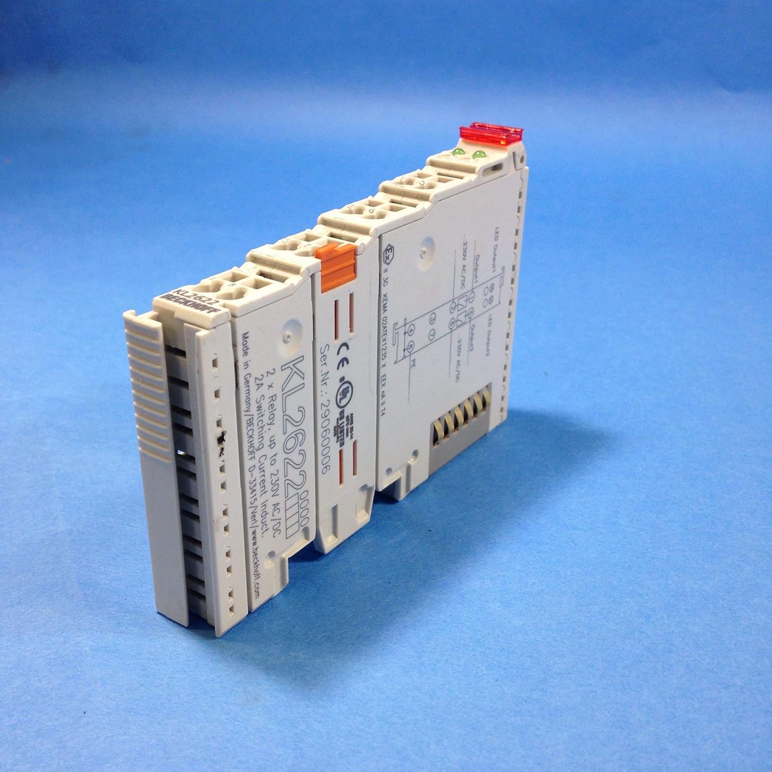
Figuur 3.1: Hoekig view of the Beckhoff KL2622 Relay Output Terminal. This image shows the overall form factor, the terminal block connections, and the product labeling on the side.
The terminal features a compact design for DIN rail mounting and integrates seamlessly into existing Beckhoff I/O systems. The wiring diagram and specific product information are printed directly on the device housing for quick reference.

Figuur 3.2: Top view of the KL2622, highlighting the integrated wiring diagram for Output 1 and Output 2, along with the power supply connections and protective earth (PE). The product model number and serial number are also visible.
4. Spesifikasies
| Parameter | Waarde |
|---|---|
| Model | KL2622 |
| Aantal kanale | 2 |
| Uitset tipe | Aflos uitset |
| Skakelstroom | Up to 2 A per channel |
| Skakel Voltage | Up to 230 V AC/DC |
| Bedrading | 4-wire connection (for power and outputs) |
| Vervaardiger | Beckhoff |
| Produk afmetings | Ongeveer 3 x 4 x 1 duim (7.6 x 10.2 x 2.5 cm) |
| Gewig | Ongeveer 1.51 pond (0.68 kg) |
5. Opstelling en installering
5.1 Montering
The KL2622 terminal is designed for mounting on a standard 35 mm DIN rail. It should be snapped onto the DIN rail alongside a bus coupler and other Bus Terminals, ensuring proper mechanical and electrical connection.
5.2 Bedrading
Before wiring, ensure all power supplies are disconnected. The KL2622 features screwless terminals for quick and secure wiring. Refer to the diagram printed on the terminal and Figure 5.1 for connection details.

Figuur 5.1: Kant view of the KL2622, illustrating the terminal block connections. Wires are inserted into the openings and secured by pressing down the orange tab.
- Kragtoevoer: Connect the 230 V AC/DC power supply to the designated terminals. Ensure correct polarity if using DC.
- Uitset 1: Connect the load for Output 1 to the corresponding terminals.
- Uitset 2: Connect the load for Output 2 to the corresponding terminals.
- Protective Earth (PE): Ensure the protective earth connection is properly made to the PE terminal, if applicable to your system.
The terminal supports 4-wire connections, meaning separate connections for the power supply and each output, allowing for independent control and isolation.
6. Operasie
Once installed and wired correctly, the KL2622 operates under the control of the connected bus coupler and the higher-level control system (e.g., PLC). The relay outputs are switched based on the digital commands received from the control system.
6.1 LED-aanwysers
Each output channel on the KL2622 is equipped with an LED indicator:
- LED AAN: Indicates that the corresponding relay output is active (closed).
- LED af: Indicates that the corresponding relay output is inactive (open).
These LEDs provide a visual confirmation of the output status, aiding in commissioning and troubleshooting.
7. Onderhoud
The Beckhoff KL2622 is designed for maintenance-free operation. However, periodic inspection of the wiring connections and the terminal's physical condition is recommended to ensure continued reliable performance.
- Skoonmaak: If necessary, clean the exterior of the terminal with a soft, dry, lint-free cloth. Do not use abrasive cleaners or solvents.
- Verbindingskontrole: Periodically verify that all wire connections are secure and free from corrosion.
- Omgewingstoestande: Verseker dat die bedryfsomgewing binne die gespesifiseerde temperatuur- en humiditeitsreekse bly.
No internal maintenance or user-serviceable parts are present. Any repairs should be handled by authorized Beckhoff service personnel.
8. Probleemoplossing
This section addresses common issues that may arise during the operation of the KL2622 terminal.
| Probleem | Moontlike oorsaak | Oplossing |
|---|---|---|
| Output LED does not illuminate. |
|
|
| Connected load does not switch. |
|
|
| Terminal not recognized by bus coupler. |
|
|
9. Waarborg en Ondersteuning
Beckhoff Automation GmbH & Co. KG provides a standard warranty for its products. For specific warranty terms and conditions, please refer to the official Beckhoff website or contact your local Beckhoff sales and support representative.
For technical support, product inquiries, or service requests, please visit the official Beckhoff webwebwerf by www.beckhoff.com of kontak hul kliëntediensafdeling.