1. Inleiding
This manual provides detailed instructions for assembling and operating your Gikfun EK1939 4-Bit Digital LED Soldering Clock Kit. Designed for electronic learners and DIY enthusiasts, this kit offers a practical soldering experience and results in a functional digital clock. Please read all instructions carefully before beginning assembly.

Image 1.1: The Gikfun EK1939 4-Bit Digital LED Soldering Clock Kit.
2. Veiligheidsinligting
Always prioritize safety when working with electronic components and soldering equipment. Failure to follow safety guidelines can result in injury or damage to the product.
- Ensure your workspace is well-ventilated to avoid inhaling solder fumes.
- Wear appropriate eye protection (safety glasses) to shield your eyes from solder splashes or flying debris.
- Soldering irons become extremely hot. Handle with care to prevent burns. Always place the iron in a suitable stand when not in use.
- Keep all components and tools out of reach of children and pets.
- Disconnect power before making any adjustments or repairs to the assembled circuit.
3. Pakketinhoud
Verify that all the following components are included in your kit before starting assembly:

Image 3.1: All components included in the Gikfun EK1939 kit.
- Printed Circuit Board (PCB)
- 4-Digit 7-Segment LED Display
- Microcontroller IC (STC11F02)
- IC-aansluiting
- Weerstande (verskeie waardes)
- Capacitors (electrolytic and ceramic)
- Kristal ossillator (12MHz)
- Transistors (9015)
- Push Buttons (S1, S2, S3)
- Battery Holder (for 3x AA batteries)
- Verbindingsdrade
4. Monteer-instruksies
Follow these steps carefully to assemble your digital clock kit. It is recommended to solder smaller components first, working your way up to larger ones.
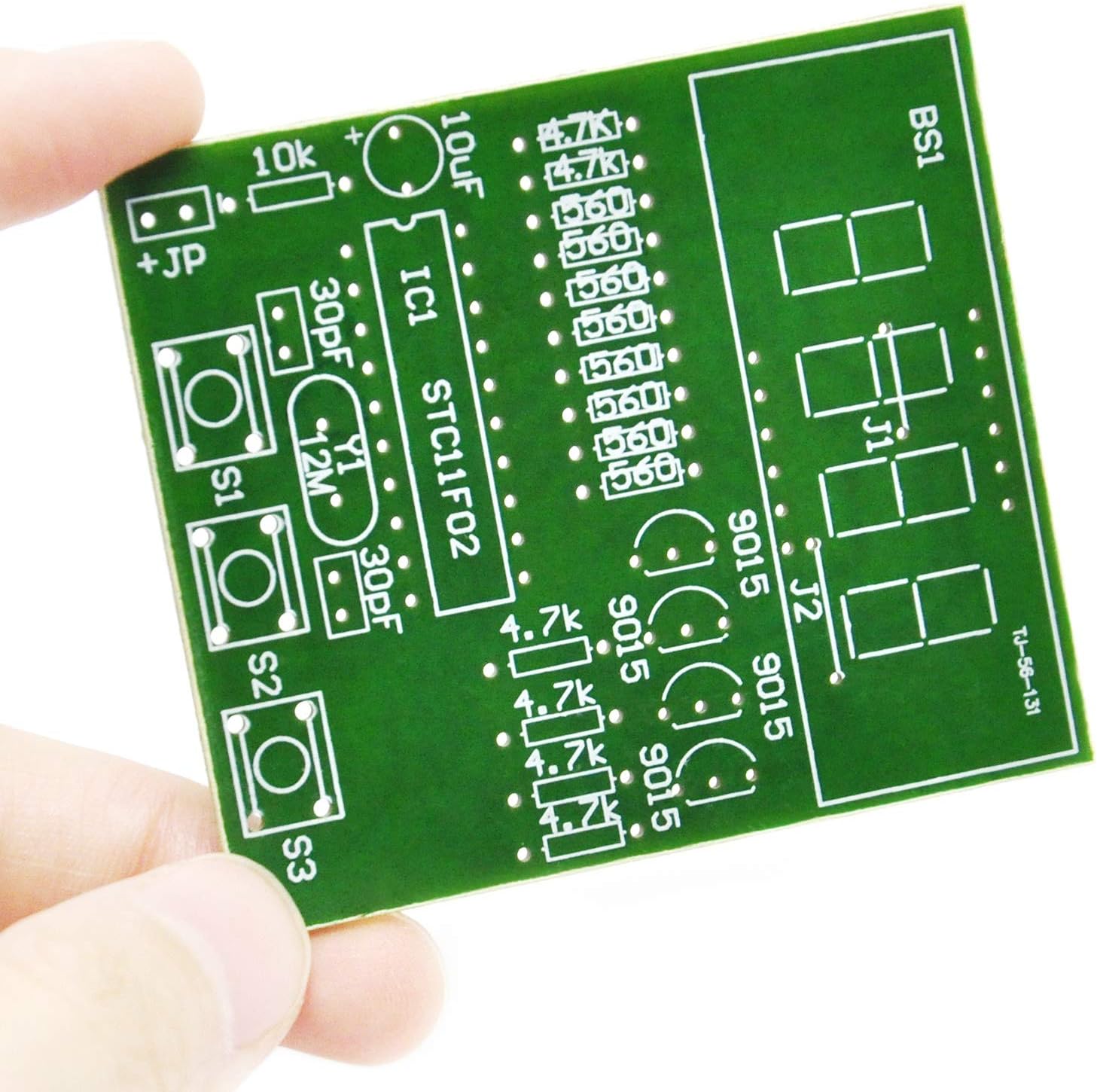
Beeld 4.1: Voorkant view of the Printed Circuit Board (PCB) with component placement markings.

Prent 4.2: Agter view of the PCB, showing solder pads and traces.

Image 4.3: Circuit schematic diagram for reference during assembly.
- Komponentidentifikasie: Before soldering, identify all components and their corresponding locations on the PCB using the provided markings and schematic. Pay attention to polarity for electrolytic capacitors and ICs.
- Soldeerweerstande: Begin by soldering all resistors. Resistors are not polarized, but ensure you place them in their correct value positions.
- Soldeerkondensators: Solder the ceramic capacitors (non-polarized) and then the electrolytic capacitors. Let wel: Electrolytic capacitors have polarity; ensure the longer lead (positive) goes into the '+' marked hole, or match the stripe on the capacitor body to the PCB marking.
- Solder Crystal Oscillator and Transistors: Solder the 12MHz crystal oscillator and the 9015 transistors. Ensure the flat side of the transistor matches the outline on the PCB.
- Solder IC Socket: Solder the IC socket onto the PCB. Ensure the notch on the socket aligns with the notch marking on the PCB. This allows for easy replacement of the IC if needed and protects it from soldering heat.
- Solder Push Buttons: Solder the three push buttons (S1, S2, S3) into their designated spots.
- Connect J1 and J2 Jumpers: Belangrike stap: Before soldering the 4-digit LED display, ensure that the J1 and J2 jumper connections on the PCB are bridged with a short piece of wire or solder. These jumpers are essential for the display to function correctly. Refer to Image 4.1 for their location.
- Solder 4-Digit LED Display: Carefully align the pins of the 4-digit LED display with the holes on the PCB and solder it into place. Ensure it is flush with the board.
- Insert Microcontroller IC: Once the IC socket has cooled, carefully insert the STC11F02 microcontroller IC into its socket. Ensure the notch on the IC aligns with the notch on the socket and PCB.
- Koppel Batteryhouer: Solder the red wire from the battery holder to the '+' pad and the black wire to the '-' pad on the PCB.
- Finale inspeksie: Thoroughly inspect all solder joints for any cold joints (dull, lumpy solder), solder bridges (shorts between pads), or unsoldered pins. Ensure all components are correctly oriented.
Video 4.1: An official video demonstrating the assembly and basic function of the Gikfun 4-Bit Digital LED Soldering Clock Kit.
5. Bedryfsinstruksies
Once assembled, your Gikfun EK1939 clock kit is ready for operation.

Image 5.1: The fully assembled Gikfun EK1939 clock kit displaying the time.
- Krag aan: Insert 3x AA batteries (not included) into the battery holder. Ensure correct polarity. Connect the battery holder to the PCB if not already done. The clock display should light up.
- Setting Hours: Druk knoppie S2 to advance the hour. Holding S2 down will accelerate the hour adjustment.
- Setting Minutes: Druk knoppie S3 to advance the minute. Holding S3 down will accelerate the minute adjustment.
- Herstel funksie: Knoppie S1 typically serves as a reset function, restarting the clock or clearing settings.
- Tydformaat: The clock displays time in a 24-hour (military) format.
6. Onderhoud
Proper maintenance ensures the longevity and reliable operation of your clock kit.
- Battery vervanging: When the display dims or the clock stops keeping accurate time, replace the AA batteries. Ensure all three batteries are replaced simultaneously with fresh ones.
- Skoonmaak: Use a soft, dry, lint-free cloth to gently wipe the PCB and LED display. Avoid using liquid cleaners or abrasive materials, as these can damage components or the PCB traces.
- Berging: If storing the kit for an extended period, remove the batteries to prevent leakage and potential damage to the battery holder and PCB.
7. Probleemoplossing
If you encounter issues with your Gikfun EK1939 clock kit, refer to the following troubleshooting guide:
- Vertoning verlig nie:
- Check battery connections and ensure batteries are inserted with correct polarity and have sufficient charge (3V-6V total).
- Verify all solder joints, especially for the LED display, IC socket, and power connections. Look for cold joints or solder bridges.
- Confirm that the J1 and J2 jumper connections are properly bridged. This is a common point of failure if the display is not working.
- Ensure the microcontroller IC is correctly seated in its socket and oriented properly.
- Incorrect or Unstable Time Display:
- Check the crystal oscillator (12MHz) and its associated ceramic capacitors for proper soldering and connection.
- Ensure the power supply is stable. Low battery voltage can affect timekeeping accuracy.
- Knoppies reageer nie:
- Inspect the solder joints for the S1, S2, and S3 push buttons.
- Ensure there are no shorts around the button pins.
- Components Getting Hot:
- Immediately disconnect power. This usually indicates a short circuit.
- Carefully inspect the entire PCB for solder bridges, incorrect component placement, or reversed polarity on polarized components.
8. Spesifikasies
| Kenmerk | Detail |
|---|---|
| Modelnommer | EK1939 |
| Handelsmerk | Gikfun |
| Aanbod Voltage | 3V ~ 6V |
| PCB Grootte | 50 mm x 19 mm (1.97 x 0.75 duim) |
| Produk afmetings | 1.97 x 0.75 x 7.48 duim (saamgestel) |
| Item gewig | 0.81 onse |
| Aanbevole ouderdom | 6 months and up (Note: Soldering requires adult supervision) |
9. Waarborg en Ondersteuning
Gikfun products are designed for quality and performance. For any questions regarding assembly, operation, or if you require technical assistance, please contact the Gikfun_Official_Store directly through the Amazon platform where you purchased the product.
Please refer to the seller's return policy for information on warranties and returns.