1. Inleiding
This manual provides detailed instructions for the installation, operation, and maintenance of the Supermicro MBD-X10SLH-F-O uATX Server Motherboard. Please read this manual thoroughly before beginning installation to ensure proper setup and to maximize the performance and longevity of your system. This motherboard is designed for server applications, supporting Intel LGA1150 processors and DDR3 memory.
2. Produk verbyview
The Supermicro MBD-X10SLH-F-O is a high-performance uATX server motherboard featuring the Intel C226 chipset. It is engineered for reliability and efficiency in server environments.
Sleutel kenmerke:
- CPU-aansluiting: LGA1150, supporting Intel Xeon E3-1200 v3/v4 series, 4th/5th Gen Core i3, Pentium, Celeron processors.
- Geheue: 4x 204-pin DDR3-1600 SODIMM slots, supporting up to 32GB ECC/non-ECC Unbuffered memory.
- Uitbreidingsgleuwe: 1x PCI-Express 3.0 x16, 1x PCI-Express 2.0 x8, 1x PCI-Express 2.0 x4.
- Berging: 6x SATA3 (6Gbps) ports.
- Verbinding: Dual Gigabit Ethernet LAN ports (2x RJ45) and 1x Dedicated IPMI LAN port (RJ45).
- USB-poorte: 4x USB 3.0 ports, 6x USB 2.0 ports.
- Video-uitset: 1x VGA port.
- Vormfaktor: uATX (9.6" x 9.6").
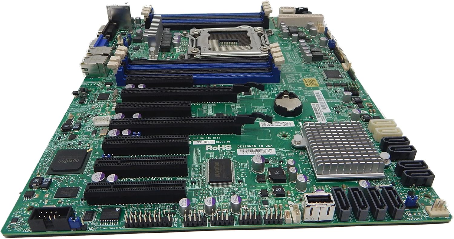
Figuur 2.1: Van onder na onder view of the Supermicro MBD-X10SLH-F-O motherboard, showing the CPU socket, RAM slots, and various expansion slots.

Figuur 2.2: Hoekig view of the motherboard, highlighting the LGA1150 CPU socket and the four DDR3 SODIMM memory slots.

Figuur 2.3: Agter view of the Supermicro MBD-X10SLH-F-O motherboard, displaying the I/O panel with USB, VGA, LAN, and IPMI ports.

Figuur 2.4: Close-up view of the motherboard, showing the six SATA3 ports and other onboard connectors.
3. Spesifikasies
| Kenmerk | Spesifikasie |
|---|---|
| Handelsmerk | Supermikro |
| Model Naam | MBD-X10SLH-F-O |
| CPU-sok | LGA 1150 |
| Chipset Tipe | Intel C226 |
| Versoenbare verwerkers | Intel Core i3-4xxx, i5-4xxx, i7-4xxx, i3-5xxx, i5-5xxx, i7-5xxx, Intel Xeon E3-1200 v3/v4 series |
| RAM geheue tegnologie | DDR3 |
| Geheue spoed | 1600 MHz |
| Max RAM Supported | 32 GB |
| Aantal USB 2.0-poorte | 6 |
| Aantal USB 3.0-poorte | 4 |
| SATA-poorte | 6x SATA3 (6Gbps) |
| Uitbreidingsgleuwe | 1x PCIe 3.0 x16, 1x PCIe 2.0 x8, 1x PCIe 2.0 x4 |
| Vormfaktor | uATX |
| Afmetings (LxBxH) | 14 x 11 x 3.5 duim |
| Item gewig | 3.52 onse |
4. Opstelling
Before beginning installation, ensure your system is powered off and disconnected from the power source. Always handle the motherboard by its edges to avoid static discharge.
4.1. SVE-installasie
- Lig die hefboom van die SVE-sokkel liggies op.
- Align the CPU with the socket, ensuring the gold triangle on the CPU matches the triangle on the socket.
- Plaas die SVE versigtig in die sok sonder om dit te forseer.
- Lower the socket lever and secure it.
- Wend termiese pasta aan en installeer die SVE-verkoeler volgens die vervaardiger se instruksies.
4.2. Geheue-installasie
- Maak die knippies aan beide kante van die DIMM-gleuf oop.
- Align the memory module's notch with the key in the DIMM slot.
- Druk stewig aan beide kante van die geheuemodule totdat die knippies in plek klik.
4.3. Installasie van uitbreidingskaart
- Remove the corresponding slot cover from your chassis.
- Align the expansion card with the desired PCIe slot.
- Press down firmly until the card is fully seated.
- Secure the card with a screw or retention clip.
4.4. Stoortoestelverbinding
- Koppel die een kant van 'n SATA-datakabel aan 'n SATA-poort op die moederbord.
- Connect the other end of the SATA data cable to your storage device (HDD/SSD).
- Koppel 'n SATA-kragkabel vanaf jou kragtoevoer na die stoortoestel.
4.5. Kragverbindings
- Koppel die 24-pen ATX-hoofkragkonnektor van jou kragtoevoer aan die moederbord.
- Koppel die 8-pen (of 4-pen) ATX 12V SVE-kragkonnektor aan die moederbord.
4.6. Voorpaneelverbindings
Connect the front panel headers (Power LED, HDD LED, Power Switch, Reset Switch, USB, Audio) to the corresponding pins on the motherboard. Refer to the motherboard's silkscreen labels for correct pin orientation.
5. Bedryfsinstruksies
5.1. Aanvanklike opstart
- After all components are installed and connected, connect the power cord to your power supply and turn on the power switch.
- Press the power button on your chassis.
- Die stelsel behoort aan te skakel, en jy behoort 'n skerm op jou monitor te sien.
5.2. BIOS/UEFI-toegang
To enter the BIOS/UEFI setup utility, press the designated key (commonly DEL or F2) during the initial boot sequence. The exact key may vary; observe the on-screen prompts.
5.3. IPMI Remote Management
This motherboard features a dedicated IPMI LAN port for remote management. To access the IPMI interface, connect the IPMI LAN port to your network. Obtain the IP address assigned to the IPMI interface (either from BIOS or a network scan) and access it via a web browser from another computer on the same network. Java may be required for remote console functionality.
6. Onderhoud
Gereelde onderhoud help om die stabiliteit en lang lewensduur van jou moederbord en stelsel te verseker.
- Stofverwydering: Maak gereeld stof van die moederbord en komponente skoon met saamgeperste lug. Maak seker dat die stelsel afgeskakel en ontkoppel is voordat jy dit skoonmaak.
- Kabelbestuur: Ensure all cables are neatly routed and secured to prevent obstruction of airflow and accidental disconnections.
- BIOS/Firmware-opdaterings: Gaan die Supermicro na website for the latest BIOS and IPMI firmware updates. Follow the provided instructions carefully. Note that IPMI BIOS upgrades may require a separate license. Always update BIOS before IPMI firmware.
- Komponentkontroles: Occasionally inspect all connections (power, data, expansion cards) to ensure they are securely seated.
7. Probleemoplossing
Hierdie afdeling spreek algemene probleme aan wat jy mag teëkom.
7.1. System Fails to Boot
- Gaan kragverbindings na: Ensure the 24-pin ATX and 8-pin CPU power connectors are securely attached.
- Herplaas komponente: Remove and re-install the CPU, memory modules, and any expansion cards to ensure they are properly seated.
- Vee CMOS uit: Refer to your motherboard's detailed manual for instructions on how to clear the CMOS, which can resolve boot issues caused by incorrect BIOS settings.
- Minimum konfigurasie: Try booting with only essential components (CPU, one RAM stick, power supply, and display) to isolate the problem.
7.2. Fan Speed Issues
Some low RPM, high-efficiency fans may not be accurately detected by the motherboard's fan controller, leading to erratic fan speed behavior (e.g., fans spinning up to max RPM). This is often due to the controller expecting server-grade fans with higher RPM ranges.
- BIOS-instellings: Check BIOS settings for fan control options. Adjust fan curves or modes if available.
- 3-Pin vs. 4-Pin Fans: If using 4-pin PWM fans that exhibit this behavior, consider using 3-pin adapters if available with your fans. This can sometimes provide a more stable, albeit less precise, fan control.
- IPMI Fan Control: While IPMI offers fan control, it may have limitations for low RPM fans.
7.3. SATA Port Obstruction
When installing a full-size graphics processing unit (GPU), some SATA ports may become physically blocked or difficult to access.
- Beplan vooruit: Connect SATA cables to the necessary ports before installing large expansion cards.
- Angled SATA Cables: Use SATA cables with angled connectors if straight connectors are obstructed.
- Alternative Ports: Utilize any unblocked SATA ports first.
8. Waarborg- en Ondersteuningsinligting
For detailed warranty information, including terms, conditions, and duration, please refer to the official Supermicro website or the warranty card included with your product. For technical support, driver downloads, and additional documentation, visit the Supermicro support portal.
Supermicro Official Webwebwerf: www.supermicro.com