1. Inleiding
This manual provides essential information for the proper installation, operation, and maintenance of your VDO Temperature Sender, Model 323-478. This sensor is designed to accurately measure temperatures within a range of 32°F to 250°F (0°C to 120°C) and transmit an electrical signal to a compatible gauge or control unit. It features a 1/2-14 NPTF thread for secure mounting and a floating ground design for versatile electrical integration.
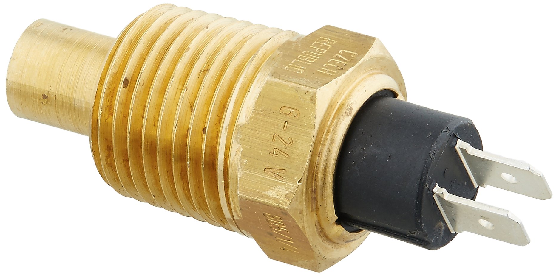
Figuur 1: VDO Temperature Sender. A close-up view of the VDO Temperature Sender, showing its brass threaded body, hexagonal base, and the black electrical connector with two flat terminals. Markings 'CZECH REPUBLIC' and '6-24 V' are visible on the hexagonal part.
2. Spesifikasies
| Eienskap | Waarde |
|---|---|
| Handelsmerk | VDO |
| Model Naam | 323-478 |
| Deelnommer | 323 478 |
| Meetreeks | 32°F - 250°F / 0°C - 120°C |
| Laer temperatuurgradering | 120 grade Celsius |
| Boonste temperatuurgradering | 250 grade Fahrenheit |
| Montage tipe | Flange Mount (1/2-14 NPTF thread) |
| Uitset tipe | Elektriese sein |
| Materiaal | Plastic (connector), Brass (body) |
| Item gewig | 2.88 onse |
| Itemafmetings (L x B x H) | 7.5 x 5 x 1 duim |
| Voorgestelde gebruikers | Unisex-volwassene |
| UPC | 754059002972 |
3. Opstelling en installering
Proper installation is crucial for the accurate and reliable operation of your VDO Temperature Sender. Always ensure safety precautions are followed.
3.1 Veiligheidsmaatreëls
- Disconnect the vehicle's battery or power source before beginning any electrical work.
- Allow the engine or system to cool down completely if installing in a hot environment (e.g., engine coolant system).
- Dra gepaste persoonlike beskermende toerusting (PPE), soos handskoene en oogbeskerming.
3.2 Montageplek
Identify a suitable mounting location that provides an accurate temperature reading of the fluid or component you wish to monitor. This typically involves a threaded port in the engine block, cylinder head, radiator, or a dedicated temperature sensor adapter.
3.3 Meganiese installasie
- Ensure the mounting port is clean and free of debris.
- Apply a suitable thread sealant (e.g., PTFE tape or liquid thread sealant) to the 1/2-14 NPTF threads of the sender. This helps prevent leaks and ensures a good seal.
- Carefully thread the sender into the mounting port by hand to avoid cross-threading.
- Using an appropriate wrench on the hexagonal base, tighten the sender until snug. Do not overtighten, as this can damage the sender or the mounting port. Refer to the vehicle or system's service manual for specific torque specifications if available.
3.4 Elektriese aansluiting
The VDO Temperature Sender features a floating ground design, meaning its electrical connection is isolated from the sender's body. This allows for flexible wiring configurations.
- Connect the appropriate wiring harness to the two flat terminals on the sender's electrical connector. Ensure a secure connection.
- Connect the other end of the wiring harness to your compatible temperature gauge or control unit, following its specific wiring diagram. Typically, one terminal connects to the gauge's signal input, and the other connects to a dedicated ground or the gauge's ground reference.
- Maak seker dat alle verbindings stewig en behoorlik geïsoleer is om kortsluitings te voorkom.
3.5 Na-installasie kontrole
- Reconnect the battery or power source.
- Start the engine or activate the system and check for any leaks around the sender's mounting point.
- Monitor the temperature gauge or display to ensure it is providing accurate and stable readings.
4. Bedryfsinstruksies
The VDO Temperature Sender operates by converting the measured temperature into a variable electrical resistance. This resistance change is then interpreted by a connected temperature gauge or electronic control unit (ECU) to display the temperature reading.
- Temperatuurmeting: The sensor's internal thermistor changes its electrical resistance in response to temperature fluctuations.
- Seinuitset: This resistance change generates a corresponding electrical signal (typically a voltage or current variation) that is sent to the connected display or control system.
- Verenigbaarheid: Ensure the connected gauge or ECU is compatible with the VDO sender's resistance curve for accurate readings. VDO gauges are designed to work seamlessly with VDO senders.
- Bedryfsvoltage: The sender is designed to operate within a 6-24V electrical system.
Once installed and connected, the sender continuously provides temperature data as long as the system is powered and operating within its specified temperature range.
5. Onderhoud
The VDO Temperature Sender is designed for long-term, reliable operation with minimal maintenance. However, periodic checks can help ensure its continued performance.
- Visuele inspeksie: Periodically inspect the sender and its wiring for any signs of physical damage, corrosion, or leaks around the mounting point.
- Elektriese verbindings: Ensure that the electrical connections to the sender remain clean, tight, and free of corrosion. Loose or corroded connections can lead to inaccurate readings or intermittent operation.
- Skoonmaak: If necessary, gently clean the exterior of the sender with a soft cloth. Avoid using harsh chemicals or abrasive materials that could damage the sensor or its housing.
- Geen gebruikerdiensbare onderdele nie: The VDO Temperature Sender contains no user-serviceable parts. Do not attempt to disassemble or repair the unit. If the sender is faulty, it should be replaced.
6. Probleemoplossing
If you experience issues with your VDO Temperature Sender, refer to the following troubleshooting guide:
| Probleem | Moontlike oorsaak | Oplossing |
|---|---|---|
| Onakkurate temperatuurlesing |
|
|
| Geen temperatuurlesing nie |
|
|
| Temperature Reading Stuck at Max/Min |
|
|
| Fluid Leak at Sender Mount |
|
|
If troubleshooting steps do not resolve the issue, it is recommended to consult a qualified technician or contact VDO customer support.
7. Waarborg
This VDO Temperature Sender comes with a manufacturer's warranty. For specific details regarding the warranty period, coverage, and claims process, please refer to the warranty documentation included with your purchase or visit the official VDO webwebwerf. Bewaar u bewys van aankoop vir waarborgeise.
8. Ondersteuning
For technical assistance, product inquiries, or warranty support, please contact VDO customer service. You can typically find contact information on the official VDO webwebwerf of deur u produkhandelaar.
Wanneer u ondersteuning kontak, hou asseblief die volgende inligting gereed:
- Produkmodel: 323-478
- Produk-UPK: 754059002972
- Datum van aankoop
- Gedetailleerde beskrywing van die probleem